Continue to Site

Welcome to MCAD Central

Join our MCAD Central community forums, the largest resource for MCAD (Mechanical Computer-Aided Design) professionals, including files, forums, jobs, articles, calendar, and more.

Creo parametric enhancements

solidworm

Super Moderator
i was searching for enhancements for creo parametric, but couldn't find any results on PTC website, so i decided to open a thread here and invite everyone who has an experience with it, post new enhancements and maybe tips and tricks. here's three sketch enhancements thats worth mentioning:

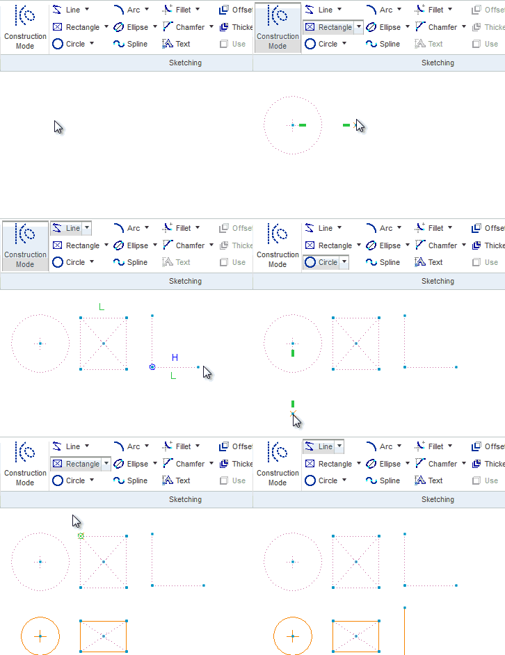
1-center rectangle

center_rectangle.gif


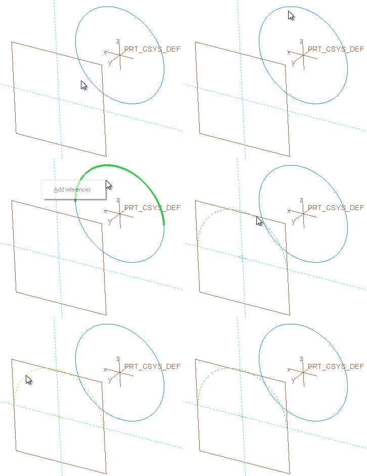
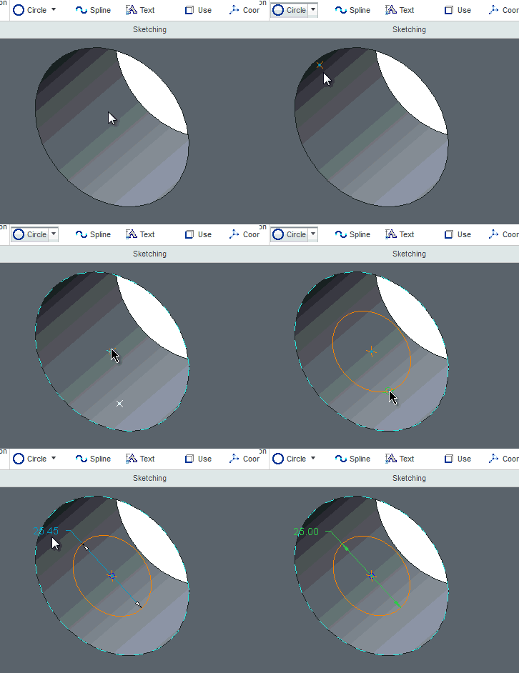
2-live references (i guess this is the correct term) : no need to goto
the references dialogbox to create sketch reference, Alt selecting
faces,edges and vertices creates references on the fly:
live_ref.gif


3-construction mode:
construction.gif
 
You never had to add refs through the ref dialog, you could use the contrain dialog to select them directly.

The construction mode looks very cool.
 
thanks Doug, i never knew that! using this new method, you can create multiple references at once too. (alt+ctrl+select) after releasing alt key, it creates sketch refs. (before pressing these keys a sketch command(line,arc,etc) should be active)


Edited by: solidworm
 
no need to go through sketch setup and references dialog box to sketch on model faces (it automatically projects the part coordinate system on the sketch plane and creates weak dims relative to it)
origin.gif


Edited by: solidworm
 
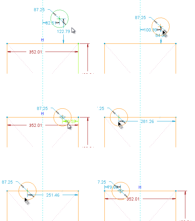
Select the center of the rectangle and Shift and you can push and pull the height & width. I was kind of hoping it would snap to a reference like in Style.

Maybe I need more time with it but drawings appear to be screwed up.
 
Greg, it works as you described! pressing shift an hovering over a sketch entity or sketch ref triggers the snap. (it works in WF5 too.)
snap.gif


Edited by: solidworm
 
so far I only wish myself to sitclose to Creo and play for a while

anyway - that is great job solidworm. I wait for more

btw - what tool do you use to record attached gifs?


Edited by: muadib3d
 
Thanks Jacek. i use camtasia to record the gifs.
a few surfacing enhancements that worths mentioning:
* remove tool can now delete surfaces from a solid and convert it into a quilt ("leave open" check box):
remove.gif

* i'm not sure if this is new, but there's a surface fitting option in "independent feature" similar to Rhino's drape surface, to drop surfaces on faceted data. it also allows to change the surface type (spline,B-spline,Bezier), degree and segmentation, through IDD interface.
a flat surface fitted on a curved stl surface.
fit-surf.png


Edited by: solidworm
 
no, N-sided patch hasn't changed.
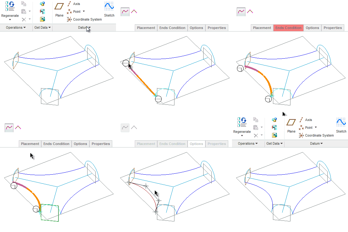
* datum curve has a dashboard and a familiar a way to specify boundary conditions at start and end of the curve. (similar to boundary blend).
curve2.gif
 
solidworm said:
no need to go through sketch setup and references dialog box to sketch on model faces (it automatically projects the part coordinate system on the sketch plane and creates weak dims relative to it)

How does it select the sketch orientation and can you change it? I know in WF4, the assumed refference for sketch orientation, particularly when using model surfaces, is not what I'd want and sometimes creates unwanted parent child relationships.

BTW - Thanks for doing this, I'm getting excited about Creo. Sounds like a huge step forward for PTC.

I wonder where Mindripper is ...
smiley36.gif
 
yeah, there might be some issues when using this automatic selection of references. i dont know how it selects a view orientation. but you can always use the old method, as the sketch setup and ref dialog box is still available. there should be a config option to enable or disable this behavour. but, the part origin should be a stable choice as a reference.
mindripper, where are you?
smiley2.gif


Edited by: solidworm
 
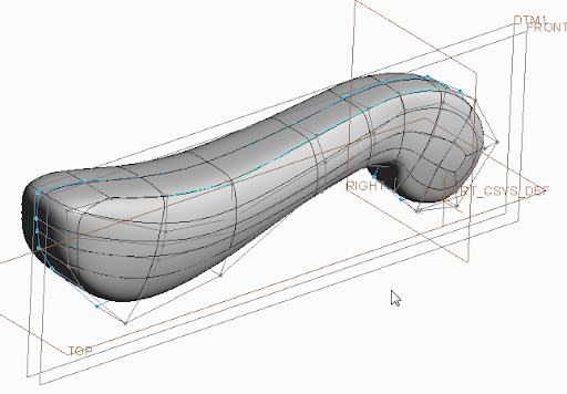
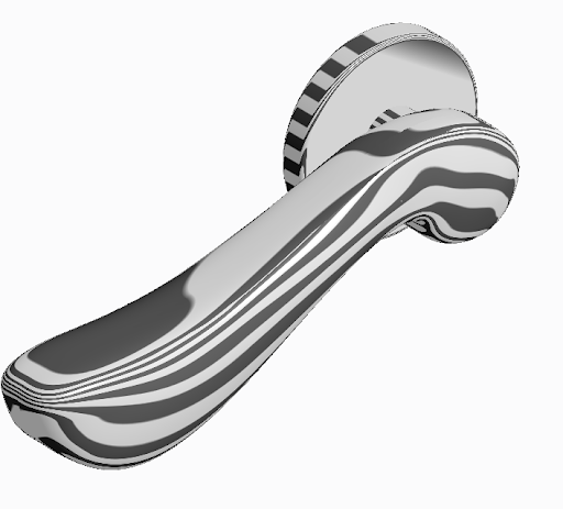
My first SubD modeling in creo guys! not that bad! i should work on making it G2 across the handle mirror plane. i started with a flat rectangular surface and modeled half of it first. (right click>view image, to see a larger image)
doorhandle.jpg


FreeStyle.png


zibra.png


Edited by: solidworm
 
What about the overall performance, is it choking your computer or does it perform well?
We noticed that WF 5.0 was choking our graphics card and I heard that the Beta version of Creo seemed slow unlesss you were on Win 7 64 bit.

Note, our computers are only 2-3 years old with decent graphics cards Nvidia FX570 or better with min 512 MB.
 
i built my PC in 2007, it's an old Pentium D 3.4 Ghz ,2G RAM, Geforce 9500GT(1Gig memory), windows 7 32bit,. the performance is is not as good as wildfire 5.0 as you mentioned, i noticed that my PC fans run faster when i use Creo(higher CPU usage) and the frame rate is less than WF5 when rotating models. but it doesn't choke the PC. at least for parts and assemblies that i have tried.
EDIT: low frame rate problem goes away when i use windows 7 basic theme.


Edited by: solidworm
 
here's an experiment i did about performance and resource usage to compare Creo parametric and WF5.0 M070. WF5.0 uses less resources in all of these test:
1- startup,no parts:
startup.png

2-opening blank part:
blank_part.png

3- hovering over blank space in a part:
HoverWhite.png


3- hovering over a cube with some fillets:
HoverModel.png
 
Creo 1.0 is definitely more demanding on the system. The
graphics are superior, especially feature previews.
 
another enhancement -
in assemblies, you can now set angle offset constraint. one
less thing for mindripper to complain about.
smiley36.gif
 
Thanks for the tips solidworm and the heads up on surface splits. Turns out drawings are OK but my system colors file wasn't. The default color scheme in Creo is black on white, and that includes drawings also.
 

Sponsor

Articles From 3DCAD World

Back
Top