Continue to Site
Follow along with the video below to see how to install our site as a web app on your home screen.
Note: This feature may not be available in some browsers.


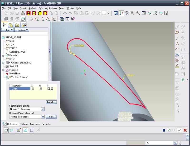

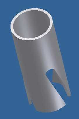
Bob_W said:Projecting the curve as shown will
cause a cut to be made in the cylinder surface that does
not maintain a constant width.