I'm trying to distribute 200 point evenly (as near as possible with anominal amount of points closest to 200)on the surface of a sphere in SolidWorks. I know of the Golden Section Spiral algorithm and some examples of code written for certain programs to calculate the coordinates of the points, but do not know how to apply it to a CAD program such as SolidWorks.
http://cgafaq.info/wiki/Evenly_distributed_points_on_sphere
http://www.enginemonitoring.org/illum/illum.html
http://www.xsi-blog.com/archives/115
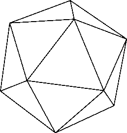
60 Points:
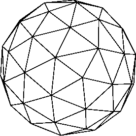
60 points:
Unfortunately I do not know how to use these programs that generate the individual x,y,z coordinates nor how to apply this algorithm to SolidWorks. Any detailed layman's help would be very appreciated.
Edited by: Kamak
http://cgafaq.info/wiki/Evenly_distributed_points_on_sphere
http://www.enginemonitoring.org/illum/illum.html
http://www.xsi-blog.com/archives/115
60 Points:
60 points:
Unfortunately I do not know how to use these programs that generate the individual x,y,z coordinates nor how to apply this algorithm to SolidWorks. Any detailed layman's help would be very appreciated.
Edited by: Kamak