bowlofnoodle
New member
Hi everybody,
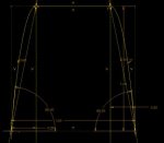
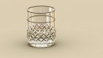
I have created a YouTube tutorial showing how to create complex sweep cut on a drinking glass.
Creo Tutorial - Advance Drinking Glass Sweep Cut Technique Part 1 - YouTube
Enjoy!
I have created a YouTube tutorial showing how to create complex sweep cut on a drinking glass.
Creo Tutorial - Advance Drinking Glass Sweep Cut Technique Part 1 - YouTube
Enjoy!
")