Continue to Site

Welcome to MCAD Central

Join our MCAD Central community forums, the largest resource for MCAD (Mechanical Computer-Aided Design) professionals, including files, forums, jobs, articles, calendar, and more.

Overwrite Dimension

sk_astroman

New member
Dear All,

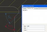
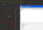
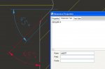
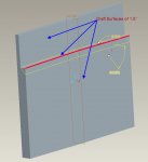
I was creating a overwrite dimension as shown in below image.
Blue dimension is shown using Show/Erase. Red dimension is created dimension. I was trying to overwrite created dimension using the dimension ID of show/erase dimension.

http://www.mcadcentral.com/attachment.php?attachmentid=5971&d=1358841555

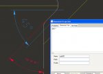
But after I save the drawing and open it, it only show ***.

http://www.mcadcentral.com/attachment.php?attachmentid=5972&d=1358841588

I'm using Pro-E Wildfire 4.0 M170. But I hope this is working with M220.

Please tell me if anything i have to modify in 'drawing options' or config.pro.

Please somebody help me to over come my issue.
 

Attachments

  • overwrite_dimension.jpg
    overwrite_dimension.jpg
    51.4 KB · Views: 36
  • overwrite_dimension_2.jpg
    overwrite_dimension_2.jpg
    51.8 KB · Views: 27
Normally created dimensions will have "ad" in their dim ID in the name field. Eg. ad15, ad156 etc. But in the attached image you entered &d941 in both places. So just create a new angle dimension in drawing and enter @o&d941:4. Leave other places as it is and enter.
 
Dear Bell,
Thank you for our reply. I thought that this would be a point of confusion for others after creating this thread.

I was just tried to change the ID whether that way may work for me.
Infact there is not a problem of changing ID of an 'Created Dimension', it should work for overwrite dimensioning.

Here I have attached corrected pictures.

http://www.mcadcentral.com/attachment.php?attachmentid=5979&d=1358918508
http://www.mcadcentral.com/attachment.php?attachmentid=5980&d=1358918519

Please somebody solve my issuse... :(
 

Attachments

  • overwrite_1.jpg
    overwrite_1.jpg
    53.7 KB · Views: 21
  • overwrite_2.jpg
    overwrite_2.jpg
    66.5 KB · Views: 21
Why don't you just redefine the feature so that it shows the way you want it to be (the red dimension)?
 
Dear Rebo,

Thank you for your reply. In fact 45° is a chamfer angle which is placed on a edge having draft of 1.5° either side of the that edge.
Please check the picture i have attached. Sorry I could not show original part, I have recreated my problem area in that picture.

So when i show the dimension I could not show as like Red highlighted dimension, its offset some where...

I hope you are understand my problem in show the dimension...

http://www.mcadcentral.com/attachment.php?attachmentid=6001&d=1360125911
 

Attachments

  • Chamfer.jpg
    Chamfer.jpg
    62.8 KB · Views: 15
Can you rearrange the feature regeneration order and try again.. Like moving chamfer up or down.. You could also use extrude cut instead of chamfer.

To find what causes this problem, in the message area, do you get any error like "highlighted entities could not be regenerated" while regenerating or saving the drawing.
 
Dear Bell,

Thank you for your reply.

Fearture oriention is a good option, I was tried it earlier too.

But my model tree has to be constructed like first modeling features, Drafts, Chamfers and Rounds...

Also when the draft is created after my chamfer some view mismatch occurs to my model. i.e. adding draft after chamfer makes difference than adding chamfer after draft.

Added to that remaining chamfers created after the above features does not give the results as my expectation.

And thanks to PTC for develping build code M220 in which my problem did not arise. I hopt there is a problem in M170 or earlier built versions.

I hope in recent version (i.e. Creo) does not have this issue.

Regards,
Karthikeyan Subbiyan.
 

Sponsor

Articles From 3DCAD World

Back
Top