Continue to Site

Welcome to MCAD Central

Join our MCAD Central community forums, the largest resource for MCAD (Mechanical Computer-Aided Design) professionals, including files, forums, jobs, articles, calendar, and more.

Feels like Monday...

dbower

New member
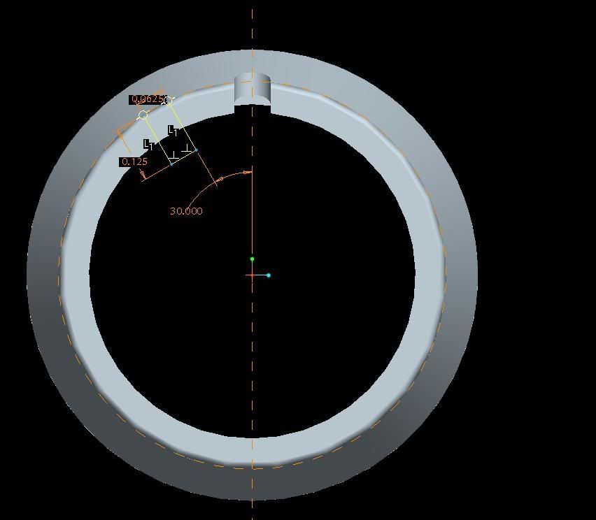
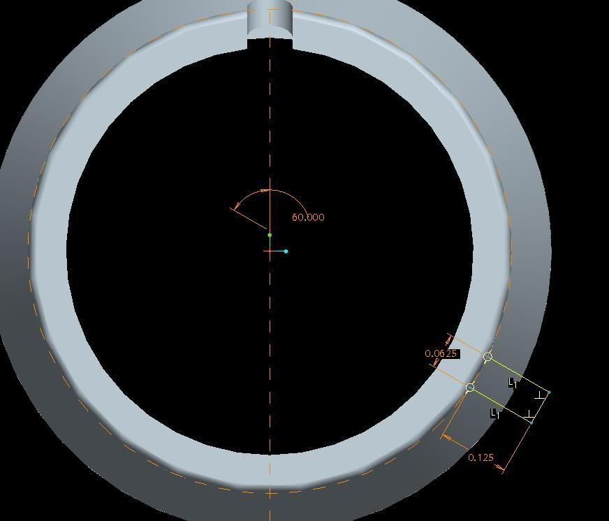
I've got a feature that is located with an an angular dimension of 30
degrees(see picture 1). When I change this to 60 degrees, it flips to the other
side of the part (see picture 2).


I know I could just recreate the feature, but I am trying to make a pattern
table of this feature, using various angle dimensions.


Any help is appreciated!


Thanks,


David
dim1-1.jpg


dim2.jpg

http://i218.photobucket.com/albums/cc54/catmandave/dim2.jpg
 
dont align in the sketch to anything. Keeps your pattern loose as a goose. And use a sketch point as the first entity in your sketch.
Edited by: design-engine
 
Make a center line (start from center of circle) and give angular dimension to it, then constrain your line perallal to it.
 
You should have set a datum-on-the-fly for your top skectch reference and then sketched the feature on the vertical centreline rather than controlling with an angular dimension in sketcher. This is a far more robust way of doing things. I suspect you may run in to trouble with your pattern when you use this dimension to control the radial positions. Also, be careful not to select a plane in your sketch; select a diameter as a referecne and then sketch a vertical centrline through the centre.
 

Sponsor

Articles From 3DCAD World

Back
Top