Continue to Site

Welcome to MCAD Central

Join our MCAD Central community forums, the largest resource for MCAD (Mechanical Computer-Aided Design) professionals, including files, forums, jobs, articles, calendar, and more.

cosine wave + surface trim (merge)

TWINTURBOTOM

New member
cosandsurface.jpg


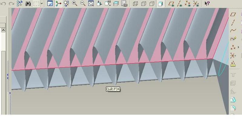
this is boundary blendfrom a cosine curve (equation curve) and that curve copied and translated to the desired off set)


above and below that are surfaces, one an elliptical section extruded (open ends) and the top is a flat surface created using the boundary blend and two parallel curves...


with the background discussed...here is my issue...I want that cosine wave to exist inside of those two other boundaries...I can not trim this damn thing!! Not sure why...Merge wasn't working for me either.....any ideas? I should be able to choose the top flat surface at the trimming object, the cosine curve as the object to be trimmed, use the keep trimming object option; and keep the cosine wave below the flat surface right? It's not working for me!!! orginally everything was created by style but I changed it all over to boundry blend surfaces hoping that might have been the issue....is pro/e being confused because the section to be trimmed passes the trimming object multple times??? any help is always appreciated....thanks guys!


it's getting late and I've had a long day...hopefully I get this squared away on a clear mind...thanks!!
 
View attachment 3014
Seems I've had similar problems in the past but can't remember
the specifics. Anyhow, if I'm following and the pic is what
you're trying to do ...? ... couple of things I'd try ...


_Extend the flat srf edges as necessary to make certain a
complete trim crv (or set of crvs, in this case) is created.
Might also look at model accuracy if that helps and it
~shouldn't~ be an issue. (If you have a very large part bounding
box for some reason it can really screw up rel tol settings.)


_Shut down, restart and try again. I have seen, on more than one
occasion, operations fail for no apparent reason and work a charm
after restarting Pro/E and may have seen an instance or two where
rebooting was necessary (wish I knew and understood why).
 
your model tree looks exactly like mine..up to the elipse.....so maybe a restart will work!...


I will check to ensure the curve is completely with in the trimming surface. The model is on my other machine so I can't update until tonight....Thank you!
 
I started from scratch and did exactly what you did with ease...I then went back to my model...didn't work;


I then started again from scratch, using the same techniques that worked for me before, only varying the frequency of the wave.....the attempt that went well made 2 crests.....I need 24 min.....at 24.....it wouldn't construct the geometry...the weird part is....when viewing the project so that you can't see the surfaces (just a sine wave and a straight line; since the other ones are directly behind from this orientation) thier is soemthing wierd.....the orign of the arrow (for the direction of what area to trim is going to happen) is not at the trimming surface...it's up in space somewhere...i wonder if this is the issue.....i'm lost as to why this works in some instances and not others when eerything is identical (technically)....GGRR...any more idea???


thanks!
 
Based on your experience with it working for 2 waves but not 24, I would definitely jack up (smaller value) the accuracy. With the bigger bounding box and the same relative accuracy it may not find the intersections properly.
 
again it worked with


y=cos(t*360*fq)
x=t*l
z=1.75
fq=2,l=2


but not


fq=24, l=24


the amount of waves per unit area is the same.....I upped the accuracty (lowered!) to .0001....still....can't intersect over the large distance...


I then made the sin wave the smaller one, and varied the trimming box....No problems what so ever.....


once the sine waves total length exceeds a certain limit...it doesn't work...and the arrows origin ends up being way above the model, instead of on the trimming surface like when it's small.....I played with the accuracty and still nothing.....what else could it be?


Thanks guys!!! keep em commin!!


I made the box big (x=24) and made the wave traverse the length of the box (x=t*24) and then varied the frequency paramerter.....it worked everytime until fq=22....I wonder what this is all about....why should this make any difference what so ever?


you guys are thinking that the accuracy is a little off so that after the wave exceeds a point the error is too large......I hope thats not the case!
Edited by: TWINTURBOTOM
 
I played with this a bit and it seems the limitatiion / bug ~is~
related to the quantity (vs. quality) of int / trim curves that
must be created. I failed above 20 cycles and could get into
modes where I'd get the results in the pic instead of being
thrown into Resolve mode. The Extrusion fails at about 25
cycles.


Those of us outside PTC programming circles can only use this as
the basis of superstition and myth, I think. `;^)


About all I can suggest is creating multiple features (or maybe
patterns) that are stable (think I'd keep a healthy buffer
between me and the failure threshold) and merge afterward.


View attachment 3020
 
yeah I ended up doing a 12 cycle and a pattern.....


Very interesting stuff, i'm not sure why this happens....in my mind generating the two curves is the hardest part for pro/e not trimming them!
 

Sponsor

Articles From 3DCAD World

Back
Top