Continue to Site

Welcome to MCAD Central

Join our MCAD Central community forums, the largest resource for MCAD (Mechanical Computer-Aided Design) professionals, including files, forums, jobs, articles, calendar, and more.

Valve/ valve seat hard stop

SKmetal7

New member
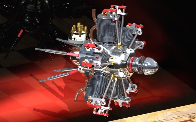
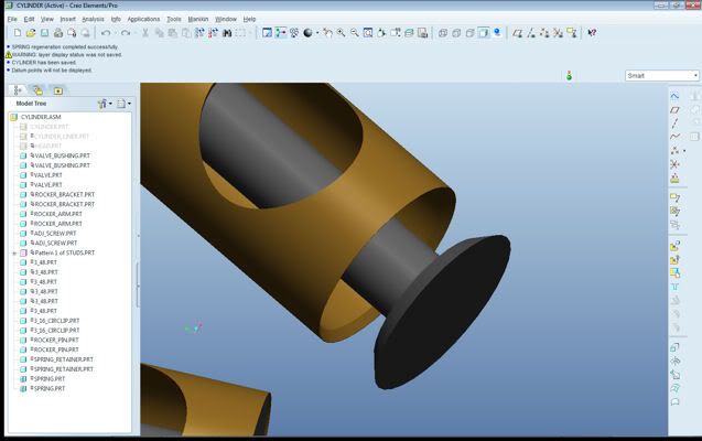
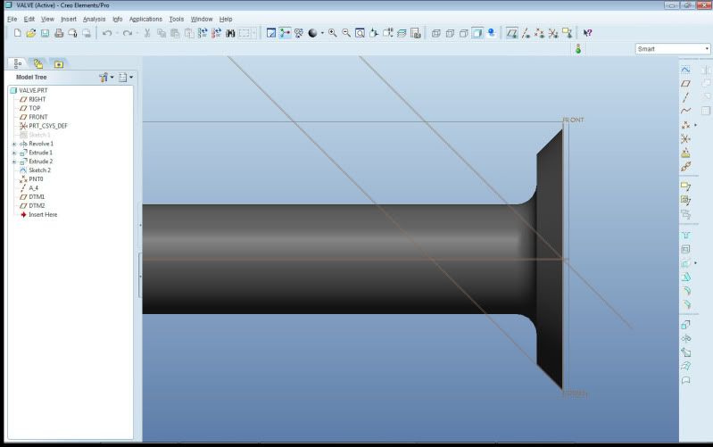
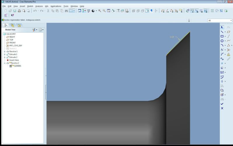
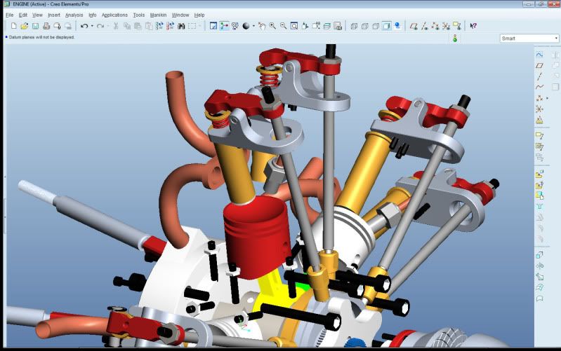
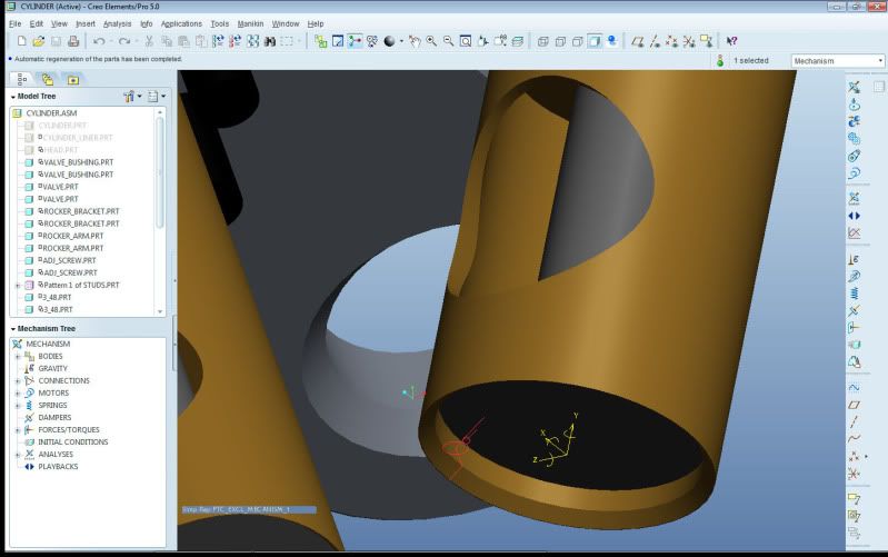
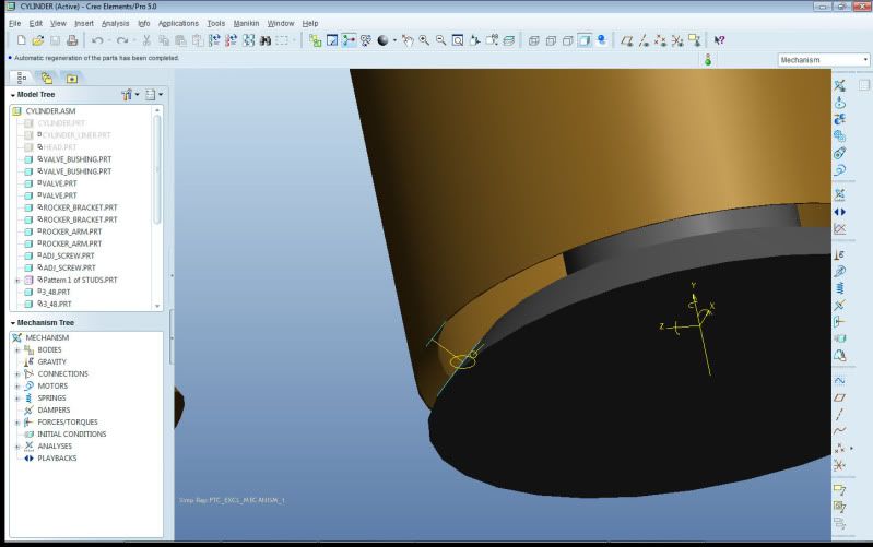
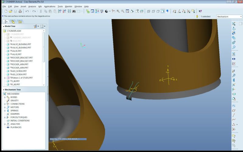
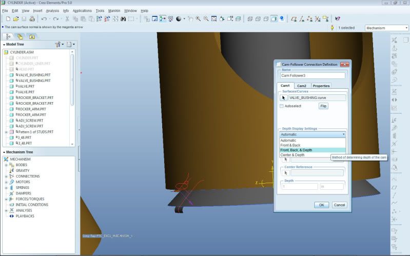
Hey guys, I need help figuring out how to define a valve/ valve seat assembly. I have the primary constraint as a cylinder, but I don't know how to make the valve stop against the valve seat. I've tried to make a cam connection, but it won't let me select the tapered surface. Maybe I'm going about this the wrong way...

valve.jpg
 
SKmetal7<br style="font-weight: normal;"><br style="font-weight: normal;">I am not an expert in this area at all, but I have done valves a couple of ways depending on the valve and sets angle. The easiest is to create a datum on each part that would represent the seated position. If the angles are the same the datums would be created through a point where the seat angle intersects the axis. Another method I have used is to extrude a cam like surface (depth doesn't matter) on each part by sketching on a sketch plane that passes through the axis of the parts. I use a silhouette edge of the valve or seat and add an arc at each end to make it more like a cam surface. Since these surfaces only curve in one plane they will work as a cam feature.

Hope this made some sense.

Bob
 
Ok, I'm trying to picture this in my head. Is the first method something like this? :

valve3.jpg

Then what kind of mechanism constraint would I use?

And is this the second method? :

valve2.jpg


It is a revolved curve, intead of a flat taper. I still won't let me select that surface for a cam. I would rather not do it that way since it doesn't represent the final valve that I will be making.

valvelinkage.jpg


So I'm trying to get all these linkages to move. I think I figured out the main cam, although CREO keeps saying the "model is disconnected" and I think it has something to do with that and the cam connection on the rocker arms; but if I can figure out how to make these valves stop against the valve seat, then I can have cam liftoff and maybe creo won't complain anymore.

I also need to figure out spring forces, to push the valve against the valve seat.
 
SK:

I found an old model where I created cam surfaces. I had used 2 methods on this one. The first was two extruded curves while the second was a flat and a curve:

This one should work for your valve seat, just hide the surfaces if you don't want to see them
Cam2.jpg


Don't know if a method like this would work for you or not. Sketch a curve on the valve and use the surface of the seat.
Cam1.jpg


Bob


Edited by: Bob_W
 
Ok, I sketched a curve, and was able to select it as cam geometry; but the valve still won't stop against the surface. I allowed cam liftoff; but why would it go passed the cam surface? Should I be concerned about Coefficient of Restitution? See video.

And is there a reason why Creo won't "Allow Assumptions" on assemblies like Pro/e used to do? I keep getting "packaged" on certain components like fasteners, and the valve itself, and have to manually regenerated the components...


valvecam.jpg


valvecam2.jpg


http://www.youtube.com/watch?v=0lPYJH4pqN4


Edited by: SKmetal7
 
I'm not sure if this would help you when using mechanism but when I assemble a valve and it is important to get it in an exact position I project a curve on the valve that has the same diameter as the seat. Then it is easy using regular constraints.
This assumes the angle on the valve and the seat are not at the same value which they arent in my cases. (Should work with the same angle too if one of the edges of the seat has contact with the valve.)
Edited by: ankarl
 
SK

I am not using Creo so I can't help with anything particular to that version. I don't know if it will help, but try putting a tangent radius curve on each end of the sketches you already have created. Does Creo require a 'depth' for those cam surfaces?

Bob
 
Ok, so I think I got it to work. It's kind of iffy though. See video.

http://www.youtube.com/watch?v=6mpsvK6x_54

valvecam3.jpg


Yes Creo does allow you to set depth of cam. It's required on flat cam surfaces, I'm not sure how it works though. I tried selecting the ends of the curves for both cams, but I'm probably not doing it right since the valve will just pass through the cam; and sometimes I get an error saying that it can't be assembled.

I also tried sweeping a surface using the curves as the trajectory, and used that as a cam surface, but the valve just moves passed the surface.

valvedepth.jpg


When you make a spring and define the force (using a force motor?), will the spring push the object (i.e. valve) when dragging the component? Or do you have to run an analysis? I'm trying to drag the rocker arm, and I want the spring to push the valve, instead of the arm pulling the valve.


Some eye candy :p :

desktop_render.jpg


Edited by: SKmetal7
 
SK

I am surprised some others haven't jumped in with comments yet. I am pretty limited in my knowledge of mechanism and have fought with the same things you are going through. To me, PTC's Mechanism is like a toy that needs a lot of work to become a real tool.

For the cam surfaces, I would simply extrude the sketch you used to make the curves as a surface. I have found several times that WF would let the cams pass through each other. Even when I would manually move the components sometimes they would pass through each other.

Springs are another thing. It has been a while but you need to use a different analysis to have spring function work. Do a search for "springs"

I joke with the guys at work, that one of the first computer programs written was the game PONG. Even it would recognize when the 'ball' would hit a wall and show it bouncing off and 30 years later it is a problem.

What did you use to render the engine?

Bob
 
I have figured out the springs, and now everything moves as it should when I do an analysis.

I used Creo's built in render engine. You can get some pretty good results, even with their limited materials/ textures selection. I think it's pretty convincing.
smiley17.gif
 
Is there a useful purpose to all this, besides "eye candy"? I see that you have adjusting screws on the rocker arms.


By the way, I would really like to see the RC that this will be in.
 
SK,

I would recommend focusing on a different area to capture valve seat limits. I've modeled hundreds of valve trains and always use the slider or cylindrical joint axis of the valve to control the seating "event". I find out exactly what the limit is of the valve's travel and assign a joint axis limit to the valve's slider/cylindrical joint. If you do enough testing or research previous work, you might even find non-linear relations to model the valve bounce correctly using external forces. Using a cam surface as you've done so far will introduce an off-centered load into the system. If your goal is to have an accurate dynamic model of the system, you'll want to limit the valve's joint movement. Be sure to create the joint axis directions properly to get "positive" valve motion during opening and establish your joint axis zero properly where the valve will contact the seat. You can use the coefficient of restitution here to help capture valve bounce. Your lift off (for valve float) will come by the way of your cam pair definition between the valve tip and the rocker pallet (or underside of a direct acting lifter) and/or the cam-follower cam pair - make this "Enable Liftoff" and you'll be able to model valve float. Set-up properly, the valve spring will take care of your closed load as well. It's possible to capture virtually all the dynamics of a hydrauliclly lashed valve train - I've had up to 24 DOF in one system to cover all locations of compliance within a hydraulic valve line with extremely high correlation to test data.

BTW - when you simply drag components with liftoff-enabled cams, you can easily get the bodies to jump/pass through each other. Running a dynamic analysis will take care of this. Also, for future questions along these lines, it might be best to post in the analysis section - this type of topic is what is normally discussed here - I just happened to stumble upon it - hope this helps,

Kaz


Edited by: Kaz Z06
 
Kaz:

That was a good reply. I was hoping that someone would come along that really knew what they were doing to help with these questions. I don't really have a use for this in my actual work, but mechanism is something I have played with just to get motion animation. I would be interested in learning a little more on this but so far it has been just by trial and error. Of course I would never trust the results of anything I would run

Any chance you have an example model that you could share/

Bob
 

Sponsor

Articles From 3DCAD World

Back
Top