Continue to Site

Welcome to MCAD Central

Join our MCAD Central community forums, the largest resource for MCAD (Mechanical Computer-Aided Design) professionals, including files, forums, jobs, articles, calendar, and more.

Extruding surface from 3d sketch?

TigWelder

New member
Question: How does one design a 3D shaped cap to seal this tank?

NewTankAttempt.jpg


I posted this question not too long ago and when I checked back several days ago to try the other techniques that were suggested, the thread disappeared and my login info no longer worked. So, I'm starting over and hope this was just a glitch.

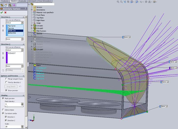
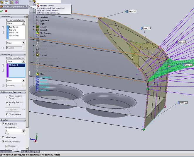
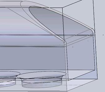
Last time, a member recommended making separate sketches (which I've placed in the picture) and using a Guide Curve to create a surface and this worked the first time. For some reason, it's not working with the new plenum shape, so I want to ask you more experienced SolidWorks users what other surfacing methods work well?


Edited by: TigWelder
 
This is one possible strategy, you can convert the end cap to sheet metal afterward if you like. Also if this fails, extend some edges to make the surfaces go through each other to ensure the surfaces can find their trim regions.

The mid-surface was used with just "find fair pairs" very easy in this example file, you might want to be more specific and select faces in your model.


2010-07-21_124227_3d_end_cap.zip
Edited by: Kevin De Smet
 
Tig,


It was me, but the website had a server crash and lost about 6 months of data or so. I can't find the file I used to show you what to do, so I'll try to recreate it this week.


Show us a screenshot of the error, or what happens when you try it, and maybe I can talk you through it.


Cheers,


Jim
 
Tig,


Here is myboundary blend. Direction 1 curves in blue, and direction 2 curves in purple. You can also do this with a loft, with the profiles in blue, and the guide curves in purple.


View attachment 5828


I remember catching some flak from some other users for using multiple sketches. Well rest assured this surtface was created with a single 3D sketch, and my curves are "open groups" selected through the selection manager. Here's my proof:


View attachment 5829


It looks like your new plenum shape has the "knee" of the sketch profile up in the curved top of the plenum, whereas before I remember it lower, in the vertical walls. If your model is parametric (as it should be) then, watch outthat the plenum shape isn't altered so much that it changes the sketch geometry -more specifically, such that it does not alter the number of segments in the sketch.


If it doesn't, then you'll need to go in and massage the sketch a bit... let me know if what I'm saying doesn't make sense.


Jim


Edited by: jimshaw
 
Thanks guys. The only problem I have is understanding how you guys made that center line, with the middle curved to match the fillet curves of each side of the tank. How are you guys doing that?
 
It's a planar line which exists on my RIGHT plane. I draw two lines at an angle on that plane, then add a fillet. The key is to make sure you go back and add all the right constraints between sketches, so the boundary surface doesn't crap out on you.


BTW - I just found the original one, and I didn't even need a third proifle in the middle. I actually only used 1 curve for the second direction:


View attachment 5834


Jim


http://www.linkedin.com/in/shawengineering
 
Jim,

Can you please explain constraining a sketch? Here is the boundary problem I'm having:

plenum2.jpg


I wish you guys taught SW courses local to me. My local community college only had 2 classes and I've taken them both
smiley36.gif
.
 
Tig,


This trick is not that obvious... Right-click on the "bottom line" in the blue direction 1 selection box on the top left of your screen there, and there'll be an option to "switch connectors". Those green/pink dots on the curves are the connectors. Depending on where along the curve you select it, it tries to determine the start and end of the curve. Here, SW just got the direction of that lastcurve backwards.


Sometimes you can even drag them along thecurve to fix them as well.


I agree, there is a global vacuum for high quality SW training. Where are you located? Perhaps we can set something up!


Jim


http://www.linkedin.com/in/shawengineering
 
After flipping the bottom line, it worked! However, Solidworks is reporting intersecting geometry error when I tried to accept the boundary with the green check-mark button.

I don't know if the original sketches have anything to do with this error, but the Top Curve and Bottom Line were created with the "Convert Entities" sketch feature. Whereas, the 2 middle horizontal lines at the upper and lower Fillet curves were sketch lines. It feels like we're close, but I'm missing something minor
smiley5.gif
...

BoundarySurfaceRebuildError.jpg


Edited by: TigWelder
 
Tig,


It's hard to tell what the "top curve" is, could you highlight it or possible share the CAD file with us?


Those two pink connectors are suspicious to me. We should see 4 green connectors and 4 pink ones. Upon closer inspection, it looks like maybe your "top curve" and top lines" curves either intersect or share endpoints?


Another thought: You may not need the "top line" curve, try removing it and see if that fixes it...


Jim
 
Tig,


This is a bit of a challenge, since you have a spline profile meeting a planar arc. I completed the boundary blend, and it is having trouble keeping the surface planar. To get around this, I created a "bounding box" around the spline, and used that to create a 4-part boundary blend.


Then I trimmed it back using the spline (the trim features need a single outline sketch to trim, so I had to add 2 sketches, but I just "converted" each half of the existing spline). Here's the curvature of the surface before & after:


View attachment 5836View attachment 5837


Here we see that we clearly have two planar surfaces joined by a constant radius bend.


Jim


http://www.linkedin.com/in/shawengineering


Edited by: jimshaw
 
And here are the files in SW09: 2010-07-26_100725_TigWelder.zip


Also, notice the sketch contraints that have been added to the 3D sketch. They are not needed, but is the best practice, as it ensures you have coincidence, tangency, and curvature at the sketch intersections. 1 minor flaw at the intersections could be the difference between a working surface, and a broken one. Here's the before & after:


View attachment 5838View attachment 5839


See if you can recreate it yourself...


Jim


http://www.linkedin.com/in/shawengineering
 

Sponsor

Articles From 3DCAD World

Back
Top