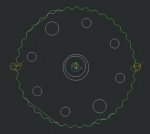
I am trying a design a Cycloidal drive mechanism wherein I am defining a couple of CAM joints. However, when I try to select the cycloidal surface as one the cam surfaces, it seems Creo is making some approximation of the surface and not taking the correct contour. Please see the attachment. Green lines are the cam profile identified by creo where as the white lines are the actual contour of the part. I am unable to fix this problem on my own. Request the experts in the forum to help me out. I would like to inform you that if the number of lobes on the part around 10, then the correct cam profile is selected.
Thank you.
Thank you.