Continue to Site

Welcome to MCAD Central

Join our MCAD Central community forums, the largest resource for MCAD (Mechanical Computer-Aided Design) professionals, including files, forums, jobs, articles, calendar, and more.

Roll bend problem

dr_gallup

Moderator
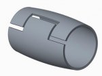
I have to model a roll pin that has a zig zag split line. I can make the part but when I try to reduce the bend radius it fails.
Capture.JPG
Here is the part with a 3 mm bend radius which is about as small as it will regen. I need to make it 2.375 mm. At some point under 3 mm I believe Pro/E thinks it starts self intersecting although it really doesn't because the notch and the tab are the same size. It can really close down to 2.25 mm radius. Any ideas on how to get this to work?
 
So I tried redefining my bend from a roll bend to an angle bend. This works better but not there yet. Since you can only bend up to 360 degrees, there is some of the tab left unbent. Maybe I can do it with 2 bends.
Capture.JPG
 
Have you tried a torroidal bend? I've used it to make tires and it works really well. This sounds like a part accuracy issue to me. It shouldn't matter what size it is if the accuracy is set to the proper size.
 
Last edited:
Have you tried a torroidal bend? I've used it to make tires and it works really well. This sounds like a part accuracy issue to me. It shouldn't matter what size it is if the accuracy is set to the proper size.

I did not try a torroidal bend, I've almost never used that feature, the interface seems to be one of the most cryptic imaginable. Does it take bend factors into account the way sheetmetal does? It's not an accuracy issue, no small surfaces. Pro/E has some build in limits on certain things like no more than 360 degrees in a bend, etc.

You have piqued my interest, torroidal bend here we come. The two bend approach has it's drawbacks such as the need to write relations to keep the bend radii the same.
 
It bends based on a selected trajectory and the overall length of the sheet being bent. It can be difficult to figure out initially but once you get the hang of the feature it is very powerful. What would take hours to do with sweeps or solid modeling when referring to making a tire, torroidal bend can do in a fraction of the time and more accurately.
 
So I made a toroidal bend but I don't understand what it did. The bent part is much bigger than the unbent part. My sheetmetal part has a radius of 2.375, the toroidal bend came out with a diameter of 8.98. I put the sketch CSYS where I expected the axis to be (help is most unhelpful about this) but the axis is nowhere near there.
Capture.JPG
 
Well. I got the radius figured out, non-intuitive as hell, typical PTC. However, you can't have any geometry that goes beyond 360 degrees so it won't work.
 
You shouldn't have to go past 360 degrees. If you were to remove the tab that sticks off of the rectangle when flat and then roll it...it doesn't have to go past 360 degrees. When you sketch the roll pin...you add the tab to the end of the rectange (past what is designated as the start or finish) on one side and add the cutout on the other. When you wrap it 360 degrees you should see exactly what you want. And you're right...its not intuitive at all and takes some practice to get it down.
 
Well see if you can get any overlapping geometry with a toroidal bend, I could not get it to. I tried with the start and finish not including the tab but as soon as I increased the angle to where the tab got close to the start it failed. Somewhere around 330 degrees in my part. The two bend sheet metal approach is working. Thanks for your help.
 
Well see if you can get any overlapping geometry with a toroidal bend, I could not get it to.

I could, right now, but then changed some dimension and it doesn't regen anymore and since the old dimensions were "weak" I don't know how to get back to that :/ Seems it's very critical but I'll check again
 
Ok, so I did it, but not the way I did it before, that was an incredible case that I'm not probably going to do again :D 
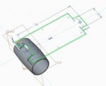
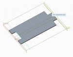
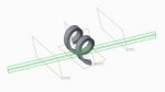
I made a part like this one, let's put the distance between the two surfaces at 350, then I place a plane at 10 from the protruding part, like in picture. Now you can do a toroidal bend "360 degree rotation" placing the profile like you see in the picture, and extending the bend from the profile plane to the datum plane created before. I know the explanation sucks, I'm sorry :/ But as you can see, it works because it bends all the geometry but "closes" the 360 degree between the start and end plane.
 

Attachments

  • 2015-11-20_145805.jpg
    2015-11-20_145805.jpg
    10.2 KB · Views: 12
  • 2015-11-20_145651.jpg
    2015-11-20_145651.jpg
    8.2 KB · Views: 10
  • 2015-11-20_145603.jpg
    2015-11-20_145603.jpg
    8.5 KB · Views: 10
It seems, anyway, that there's a limit: I made a part like this: a slanted extrusion with two planes to determine the area that's going to be "bent to 360 degree" by the toroidal bend. The parts outside the two planes are bent anyway so there's more than a 360 degree turn. Anyway the part will fail if the length of the area between the planes is LESS than HALF the length of the part, that is, you can go twice around the axis, but no more.
 

Attachments

  • 2015-11-20_152628.jpg
    2015-11-20_152628.jpg
    11.2 KB · Views: 11
Nice work Zpaolo...I thought it should be possible. That's spot on.

Thank you, I think the "two turns" limit is reasonable: you can have a tip as long as your part, and a pocket as long as your part, but you can't have a tip longer than your part or there will be an overlap. Still I don't know how I did the first one, I should've taken a picture :D
 
Have you tried making it a closed cylinder the doing a rip for the zig-zag?

Nice idea, not sure how you go about creating a closed cylinder in sheet metal (just make a solid extrude?).

In a related subject, I've got a STEP model back from a potential supplier, there are minor differences in the shape of our split line. I want to unfold his part but can't figure out how to convert it from a solid to a sheet metal part since there is no flat surface to use as the driving surface.
 
Example

Take a look at the attached file. I am pretty sure this is what you are looking for.
 

Attachments

  • test.prt.zip
    58.1 KB · Views: 6
In a related subject, I've got a STEP model back from a potential supplier, there are minor differences in the shape of our split line. I want to unfold his part but can't figure out how to convert it from a solid to a sheet metal part since there is no flat surface to use as the driving surface.

You shouldn't need a flat surface to use as a driving surface. Import and convert to sheetmetal. Prompt for Driving surface, select the outer surface and it should convert. If not, something else is wrong. Faces aren't parallel or side edges aren't perpendicular to the driving surface.
 
You shouldn't need a flat surface to use as a driving surface. Import and convert to sheetmetal. Prompt for Driving surface, select the outer surface and it should convert. If not, something else is wrong. Faces aren't parallel or side edges aren't perpendicular to the driving surface.

In that case the first feature is a sheet metal feature. If you have import geom it's not sheet metal and it won't accept the outer (or inner) surface. The geom is good, the Pro/E is weak. The end faces are not parallel because it's not a full 360 degree bend. The part has to be able to close down when it's pressed in.
 

Attachments

  • 00047110.zip
    19.2 KB · Views: 4

Sponsor

Articles From 3DCAD World

Back
Top