Continue to Site

Welcome to MCAD Central

Join our MCAD Central community forums, the largest resource for MCAD (Mechanical Computer-Aided Design) professionals, including files, forums, jobs, articles, calendar, and more.

Surfacing or Round guru help

Hello Forum,

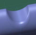
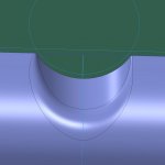
I've got this stubborn round that does not want to cooperate. This is a variable round that is using the C2 Continuous option. You will notice one side of the round is different from the other. I want the left side to look like the right (see attached images). But when I add the additional round to the left side, it fails. Is there an obvious reason why it may be failing that I'm not seeing? What other way could I create this this geometry? I am using Creo 2. I know just creating half the geometry and doing a mirror is an option. But doing that will create a mess in the model I was hoping to avoid. I also want to learn other ways of skinning this cat.

Thanks,

Victor
cam_area-3.JPGcam_area-2.JPGcam_area-1.JPG
 
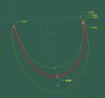
so far I noticed you made the round variable at right side contrary to left side(there are to similar values of radius at right side close to each other).

to me the difference comes from mentioned above issue and the way Pro/E approximate the radius value among inserted values
 
Thanks for the comments Jacek.

I am trying to duplicate what I have on the right, but it fails when I try to add the additional radius on the left side.

I have also tried doing half, and mirroring, but the round looks all wrong when I try that. Right now I am trying to figure out a way to do some kind of boundary blend. But creating the curve I need at the center is proving to be difficult, as I want it to be C2. The surface going left to right is created using a spline.

Thanks.
 
I do not quite understand why do you force this round to be C2?

Are you pushed to do so(C2 transition) by some external requirements?

I would avoid using C2 transitions, rounds and so forth untill I am pushed to do so. There are not that much improvement, difference at the end.

Use conic rounds instead or the simple one.
 
To achieve C2 in many direction, you would need to use style-ISDX. With the solid modeling features such as blend, sweep and blend, you can have only C2 in one direction.
 
To achieve C2 in many direction, you would need to use style-ISDX. With the solid modeling features such as blend, sweep and blend, you can have only C2 in one direction.

what exactly do you mean by "in many" direction"?

I think almost same is possible ordinary packahe of Pro/E(curve through points + BB + VSS and so forth)

BB gives you even possibility to modify surface with curvature at both ends, what is not possible in Curve throug points or spline in sketcher
 
I thought I have read through materials about the boundary blend that says that it can only be C2 in one direction.

I have just tried it out with datum curves and you can make it C2 in both directions. So you should be able to make C2 with boundary blend.
 
Thanks all for the additional comments.

Jacek, the problem occurred regardless of whether it were C2 or a regular round. But yes, it needed to be C2.

Bowlofnoodle, Jacek is right, you can do C2 in multiple directions without ISDX. The video you mentioned is a technique I have used before, but in this case would have created a lot of set-up features to get the look I wanted. Considering the time constraint I have, I didn't want to go down that road.

I did find a solution that gave me exactly what I wanted. (see image) I created a seperate set of surfaces and created the round like I did in the 1st set of photos I attached. I then trimmed the bad side off, and mirrored the good side. Merged the 2 halves and then merged that into my main surface. Worked like a charm.

Thanks again to all.

View attachment 6445
 

Sponsor

Articles From 3DCAD World

Back
Top