Continue to Site

Welcome to MCAD Central

Join our MCAD Central community forums, the largest resource for MCAD (Mechanical Computer-Aided Design) professionals, including files, forums, jobs, articles, calendar, and more.

What is the PTC Creo 'Fill Surface' (SolidWorks feature) equivalent ?

78finn

Member
I'm new to Creo, having used Solidworks for years now...But my new job requires that I use it.

I do a lot of surface work and have heard that PTC / Creo is the right choice for this type of work.

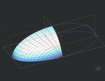
However, I cannot find a method for handling 3-Sided surfaces easily anywhere in Creo? Surely there has to be one? SolidWorks has a feature called 'Fill Surface' which handles 3-Sided surfaces easily and effortlessly and really speeds the model time up required for complex surfaces. Here is a link of it being used successfully and easily on You Tube:

SolidWorks Surfacing: Avoiding Degenerate Surfaces - SolidWorks Training by SolidWize - YouTube

So far I cant find the equivalent feature anywhere in Creo? If anyone can be of help with this, I would really appreciate it!

Cheers
 
Based on the video I'd say the STYLE feature environment is what you want to use.

Yes, I have been using a combination of conventional surface and style features to create surfaces etc. but the number of operations you have to use to end up with something not as good is very frustrating. The time difference to create the same surface in Creo VS SolidWorks is frightening! literally a few seconds in Solidworks and often hours of tweaking in Creo to get something similar. I really cant understand why people say that Creo has the edge over Solidworks in this department?
 
Ooops....my memory does not serve me well. Saw another thread which I was part of on PTC Community. I asked about this feature as an enhancement.

33. May 13, 2013 9:54 AM (in response to Brian Martin)
Re: Enhancement Requests for Creo - Summer 2013 TC Meetings
Fill Surface

It is very limited only being able to do this feature on a planar sketch. There was a fierce discussion on this topic many years ago vs Solidworks Fill Surface command http://www.mcadcentral.com/creo-modeling/16582-simple-surfacing-problem.html

The outcome surprised many of the long time users and this I believe is an excellent benchmark feature that hopefully could be introduced in Creo SURFACE. I do not use ISDX so the request is for the surface module in Foundation or what it's called nowadays.

See page 3 for the actual comparison and images of the SW Fill Surface command.


I got the following answer.

35. May 13, 2013 5:03 PM (in response to MAGNUS SALOMONSSON)
Re: Enhancement Requests for Creo - Summer 2013 TC Meetings
yes the "surface" option in ISDX works like fill option in solidworks.you can just select the curves and it would fill it with a surface.
 
This video might help for creating simple round form -> Creo Tutorial - Curvy Round Shapes - Mouse Tutorial - YouTube

Regarding 3-sided blend, in my opinion this is bad modeling practice. You should try to avoid this, the contour lines do not blend well together. Changing the model to have 4 sides to blend will make it more reliable.

This looks interesting. Thanks for the link. And yes...three sided surfaces should always avoided where possible, but I found that using the Fill command in Solidworks produced great results and therefore there was often now need to spend more time generating further geom.

So far with Creo I have been using a combination of curves created in Style and traditional boundary surfaces. I find this gives me the smoothest result. I also find that creating surfaces directly within the Style affords me less control over the surface. I have uploaded my general method so far to grab CAD (link below). Its a basic 'top hat' method...but works well. I cannot seem to get as good a result when using traditional curves / splines creating as a sketch as I can when using nurbs curves within the Style tool. I'm guessing this is because the mathematics behind the nurbs curves is better suited in producing smooth results. Does anyone else find this to be the case?

https://grabcad.com/library/avoidin...ating-clean-geometry-in-creo-2-0-parametric-1
 
This video might help for creating simple round form -> Creo Tutorial - Curvy Round Shapes - Mouse Tutorial - YouTube

Regarding 3-sided blend, in my opinion this is bad modeling practice. You should try to avoid this, the contour lines do not blend well together. Changing the model to have 4 sides to blend will make it more reliable.

This technique is good when you do not require to much control over the top surface and are just after a 'nice' shape. I have uploaded something similar to GrabCAD....using sweep and boundary features

https://grabcad.com/library/simple-smooth-mouse-style-shape-in-creo-parametric-2-0-1
 
Ooops....my memory does not serve me well. Saw another thread which I was part of on PTC Community. I asked about this feature as an enhancement.

33. May 13, 2013 9:54 AM (in response to Brian Martin)
Re: Enhancement Requests for Creo - Summer 2013 TC Meetings
Fill Surface

It is very limited only being able to do this feature on a planar sketch. There was a fierce discussion on this topic many years ago vs Solidworks Fill Surface command http://www.mcadcentral.com/creo-modeling/16582-simple-surfacing-problem.html

The outcome surprised many of the long time users and this I believe is an excellent benchmark feature that hopefully could be introduced in Creo SURFACE. I do not use ISDX so the request is for the surface module in Foundation or what it's called nowadays.

See page 3 for the actual comparison and images of the SW Fill Surface command.


I got the following answer.

35. May 13, 2013 5:03 PM (in response to MAGNUS SALOMONSSON)
Re: Enhancement Requests for Creo - Summer 2013 TC Meetings
yes the "surface" option in ISDX works like fill option in solidworks.you can just select the curves and it would fill it with a surface.

No that answer isn't right. The surface feature in ISDX (ISDX is now refereed to as Style) works pretty much the same as a boundary surface but in the looser more forgiving environment of style. It doesn't even come close to creating a 4 sided surface over 3 splines and then trimming. But Creo really should have this option. No doubt it is patent protect
 
You can just cover it up with a surface that will covering up the hole but ignoring one of the edge. Just make a surface on top where there is four boundary curve but it is position to ignoring one of the silly 3 sided gap.

Have a look for a surface kettle nose tutorial on PTC learning exchange.
 
Last edited:
No that answer isn't right. The surface feature in ISDX (ISDX is now refereed to as Style) works pretty much the same as a boundary surface but in the looser more forgiving environment of style. It doesn't even come close to creating a 4 sided surface over 3 splines and then trimming. But Creo really should have this option. No doubt it is patent protect

???

I think you should try it once again. Surface capabilities in ISDX, especially in Creo 2.0 are very high, and advanced.

There are a lot of options not available in direct surface creation tool, but in Surface edit instead.

Try it, play with it, you will be overwhelmed with dozen of posibilities.

In summary, Creo, especially in ISDX can handle 3, 5, or more n-sided surfaces same as SW does.

below you can find how ISDX nadles different types of n-sided siurfs

1.jpg
 
You can just cover it up with a surface that will covering up the hole but ignoring one of the edge. Just make a surface on top where there is four boundary curve but it is position to ignoring one of the silly 3 sided gap.

Have a look for a surface kettle nose tutorial on PTC learning exchange.

Thanks for the reply, but I'm not 100% sure what you mean here. Can you post the link to the tutorial as I have had a look and cant find that either. Cheers
 
???

I think you should try it once again. Surface capabilities in ISDX, especially in Creo 2.0 are very high, and advanced.

There are a lot of options not available in direct surface creation tool, but in Surface edit instead.

Try it, play with it, you will be overwhelmed with dozen of posibilities.

In summary, Creo, especially in ISDX can handle 3, 5, or more n-sided surfaces same as SW does.

below you can find how ISDX nadles different types of n-sided siurfs

View attachment 6350

I agree with you here. Style/ISDX is a fantastic tool...with loads of surfacing options. But I'm most specifically interested in a boundry surface derived from three curves. I know this is not the 'proper' way to model (according to PTC), but its an interesting area & one that I think SolidWorks has really got right.

There are loads of ways / mothods to model to get around this...but all of them involve more work or a completely different methodology of modeling - free form etc.
 
???

I think you should try it once again. Surface capabilities in ISDX, especially in Creo 2.0 are very high, and advanced.

There are a lot of options not available in direct surface creation tool, but in Surface edit instead.

Try it, play with it, you will be overwhelmed with dozen of posibilities.

In summary, Creo, especially in ISDX can handle 3, 5, or more n-sided surfaces same as SW does.

below you can find how ISDX nadles different types of n-sided siurfs

View attachment 6350

Also with the image you have posted up....what do the surface mesh's created look like? Do they come to a pinch point? Im my experience with this they almost certainly do, which is no good for me. This is where SolidWorks has a clear advantage as it creates a uniform surface mesh without contour lines meeting at a point in one of the three edges of the surface.
 
???

I think you should try it once again. Surface capabilities in ISDX, especially in Creo 2.0 are very high, and advanced.

There are a lot of options not available in direct surface creation tool, but in Surface edit instead.

Try it, play with it, you will be overwhelmed with dozen of posibilities.

In summary, Creo, especially in ISDX can handle 3, 5, or more n-sided surfaces same as SW does.

below you can find how ISDX nadles different types of n-sided siurfs

View attachment 6350

All of the mothods you illustrate you end up with a 'pinched' mesh as per attached image.
 

Attachments

  • prt0003.jpg
    prt0003.jpg
    71.6 KB · Views: 19
All of the mothods you illustrate you end up with a 'pinched' mesh as per attached image.

no

all of them are correct 4 sided boundaries

in the first example ISDX makes it prelimenary as ordinary 3-sided boundary, but under options you can switch the surface to 4 sided trimmed rectangle

check the pictures

1.jpg

2.jpg

3.jpg
 
no

all of them are correct 4 sided boundaries

in the first example ISDX makes it prelimenary as ordinary 3-sided boundary, but under options you can switch the surface to 4 sided trimmed rectangle

check the pictures

View attachment 6355

View attachment 6356

View attachment 6357

Hi Jacek!

Well I am prepared to admit when I am wrong! :)

Fantastic! Thats exactly what I'm looking for...

Can you tell me what settings you have switched on so that you can preview the 4 sided quilt? I can tick the 'use for 3 and 4 boundries box' but I'm not getting the mesh preview as you are showing.

Thanks again...this is exactly what I have been looking for!
 

Sponsor

Articles From 3DCAD World

Back
Top