Continue to Site

Welcome to MCAD Central

Join our MCAD Central community forums, the largest resource for MCAD (Mechanical Computer-Aided Design) professionals, including files, forums, jobs, articles, calendar, and more.

Vertical Axis Wind Turbine Blade

sthoms78

New member
Hi,

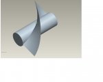
I'm trying to create a vertical blade like the one shown in the attachment, I am trying to create 3 of these blades to rotate round a cylinder but have no clue how to. Does anyone have a link to tutorial i could follow. I'm fairly new to pro e so hopefully it is not too complex.

Thanks!
 

Attachments

  • Blade.jpg
    Blade.jpg
    30.6 KB · Views: 18
When you've completed one blade, copy the surfaces and pattern about the axis, solidify first one and referevce pattern this. Apply fillets to column, if necessary, now and reference pattern this.
 
helical sweep is one way to do this, see attached file (you will need to resume features: edit-resume-resume all)
 

Attachments

  • turbine.zip
    28.7 KB · Views: 10
Axis Pattern seems to be my first thought.

The copy/paste or copy/move techniques kennpy mentioned are old techniques and work but their are now better methods.
The pattern options once required a dimension to pattern by hence Referencing a datum plane made at an angle needed to be a reference for features to be patterned. With the new and improved Pattern by Direction and by Axis options added in Wildfire2,
I used WF3+ as naming convention for my images cause I thought they were added then.
icon3.png

In your pattern type options Dimension is the usual defaut and to be able to use it you would need to reference your Swept Blend or Var Sec Sweep feature to a angle datum to pattern by it's offset angle.

With an Axis pattern all you need is an axis and proe/creo will do all the hard work needed to pattern the feature. Axis pattern gives 2 options
By angle where you specify the number of features desired and the angle between them.
By Number & Total Angle
AxisToUse | PatternCount | PatternAngle | TotalAngle
WF3%2B%40VertAxisPattern_command.PNG


After entering number of features click on the Box which normally has 360 as total angle and you'll get the correct angular spacing. You may only use one or the other. you can do pattern of 5 @72 deg or just type 5 or any other number like 9 and have proe/creo/granite auto divide and give 40deg angular spacing per 360 tot angle.
WF3%2BVt-pattern_axial-example.PNG


Michael
AT)> trajpar Proe
AT)> mcSldWrx2008 SolidWorks
 
Last edited:

Sponsor

Articles From 3DCAD World

Back
Top