Continue to Site

Welcome to MCAD Central

Join our MCAD Central community forums, the largest resource for MCAD (Mechanical Computer-Aided Design) professionals, including files, forums, jobs, articles, calendar, and more.

Cut or Trim or Subtract one part from another in assembly?

rbrookov

New member
Hello,

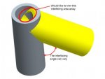
I have an Assembly where I have one tube (pipe) interfacing w/ another. Each tube (pipe) is a different modeled part.

I would like to "subtract" or "trim" the area away where the pieces overlap.

Keep in mind that the tubes can interface w/ each other in varying angles, so I'd like the cut / subtract / trim to be able to automatically update if the interfacing angle changes.

Thanks,
Rob
Pro/E WF 5.0 (Creo Elements)
 

Attachments

  • Interfering_Tubes_Question.jpg
    Interfering_Tubes_Question.jpg
    9.7 KB · Views: 26
So I found what I *thought* was the correct approach, but it turned out not to be. I used "Component Operations" (Edit: Component Operations: Cutout), but all that did was cut away where each part interfered w/ the other.

I'm not sure if I need to do something w/ Surfaces, perhaps w/ some sort of "Copy Geometry" setup, as I've never really had need to use these commands before, so I'm pretty clueless as to how to use them (if this is even the approach to take).

Any help in advising which commands to use or which approach to take will be greatly appreciated. At this stage, I'd be OK w/ even just being able to cut it once, then re-cut if the interface angle changes, as opposed to having it be smart enough to automatically update.

Thanks,
Rob
 
One simple way to achieve what you want, is to edit the part you want to cut(yellow pipe) in context of the assembly, then copy/paste (Ctrl+V/Ctrl+c) the outer surface of the other pipe into the active part,select the copied surfaces,(merge them if necessary) then use solidify/cut feature to trim the unwanted area away.
 
One simple way to achieve what you want, is to edit the part you want to cut(yellow pipe) in context of the assembly, then copy/paste (Ctrl+V/Ctrl+c) the outer surface of the other pipe into the active part,select the copied surfaces,(merge them if necessary) then use solidify/cut feature to trim the unwanted area away.

Solidworm - wow, that worked PERFECTLY!! Granted, it is a one-time, manual fix (meaning, if I were to go back & change the angle of the interface between the 2 pipes, it wouldn't automatically update), but at least I can use your method at each interface angle!!

Thanks for the tip!! Now if I can only get it to automatically update!!
 
I don't have ProE open now, but it should work when you make a change and regenerate the assembly (Ctrl+G)
 
I don't have ProE open now, but it should work when you make a change and regenerate the assembly (Ctrl+G)

By gosh you're right!! That is EXACTLY what I was looking for!! I guess I didn't realize I needed to Regen, I simply changed the angle & erroneously expected it to auto-update.

But, I went back & clicked the Regen button & it updated!!

So thank you very much!!
 
Hmmmm, very strange behavior. The screen shot I posted was of 2 example pieces I modeled up quickly. Solidworm's advice worked beautifully for the example. However, when I tried the same technique on my actual assembly, I couldn't do it because the "Edit" command did not show up.

I have a Top Level Assembly (TLA), and several Sub-Assemblies & parts within that TLA. When I went to click on the equivalent to the Yellow pipe in my example, the "Edit" command was not there. Also, I noticed that I could not do a "copy / paste" of the equivalent to the other pipe as well.

So, my question is - what is different that it worked in my small example, but not the real life one?

Any advice would be appreciated.

Thanks,
Rob
 
There are some settings in ProE which controls whether you can make external references or not. perhaps you have them set, to disallow external references:

%5BUNSET%5D.png
 
Last edited:
There are quite a few config settings that control external references and therefore part merges and cutouts:

allow_ref_scope_change YES
default_ext_ref_scope ALL
default_object_scope_setting ALL
default_object_invalid_refs COPY
ignore_all_ref_scope_settings YES
model_allow_ref_scope_change YES
scope_invalid_refs COPY


You will may still have to go into the assembly and/or the part and allow external references
 

Sponsor

Articles From 3DCAD World

Back
Top