
Hingemadness
New member
Hello to all

I'm a new SW2010 user and ive started to practice designing very simple parts and shapes. Im currently trying to create a simple hinge joint with limited success and its frustrating to say the least as im sure im missing some minor step or 2 .
This is what im trying to create:
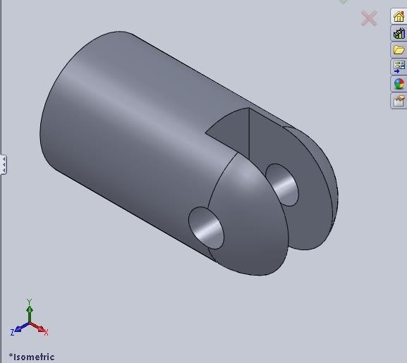
Ive been able to accomplish something similar using a Insert Part > Combine > Subtract feature but the results arent consistent nor based upon numeric input (im eyeballing the centering of the shape used to cause the negative impression).
Help would be greatly appreciated . Its a very simple part but being new to the software its causing me great frustration..
I'm a new SW2010 user and ive started to practice designing very simple parts and shapes. Im currently trying to create a simple hinge joint with limited success and its frustrating to say the least as im sure im missing some minor step or 2 .
This is what im trying to create:
Ive been able to accomplish something similar using a Insert Part > Combine > Subtract feature but the results arent consistent nor based upon numeric input (im eyeballing the centering of the shape used to cause the negative impression).
Help would be greatly appreciated . Its a very simple part but being new to the software its causing me great frustration..