michaelpaul
New member
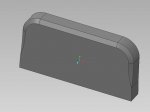
I have a swept blend I'm working on and I can't figure out how to transition to a point at my end condition. funny thing is I have an old model done with an old VSS that I can look at for reference and it works with single points at the start and end condition and I can't figure out that one either!
so i want to transition from a point to what is essentially a chamfer and then I'd like to transition back to a point.
I've attached the model if anybody takes a look at it and can tell me what to adjust. I'm sure I'm missing something simple but I can't figure it out.
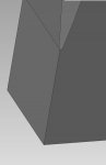
I have a single geometry point in section 1 for my start condition but anytime I try to do the same thing in my end section it tells me I have to have geometric entities in my section for it to be valid. I never got that error for my start condition.
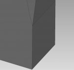
the only way I could get close was to simply transition my shape to a very small version of the chamfer but that leaves me with a very small flat surface that I don't want.
thanks
Michael
so i want to transition from a point to what is essentially a chamfer and then I'd like to transition back to a point.
I've attached the model if anybody takes a look at it and can tell me what to adjust. I'm sure I'm missing something simple but I can't figure it out.
I have a single geometry point in section 1 for my start condition but anytime I try to do the same thing in my end section it tells me I have to have geometric entities in my section for it to be valid. I never got that error for my start condition.
the only way I could get close was to simply transition my shape to a very small version of the chamfer but that leaves me with a very small flat surface that I don't want.
thanks
Michael