Continue to Site

Welcome to MCAD Central

Join our MCAD Central community forums, the largest resource for MCAD (Mechanical Computer-Aided Design) professionals, including files, forums, jobs, articles, calendar, and more.

Joining / Merging Pipes to form a V

rbrookov

New member
Hi,

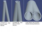
I am trying to accurately model 2 pipes formed into a "V" shape. I don't know the proper way to do this, as I have tried several different methods, and nothing seems to work (I cannot get the middle areas to be "merged" properly).

I have tried the following:

1.) modeled the pipe as an extruded part, then mirrored that part (in the same part as a new feature), then tried to shell
2.) modeled the pipe as a pipe feature, then mirrored that part (in the same part as a new feature)
3.) Created an assembly & inserted the modeled part, then used "Create New Component in Assembly Mode" - but chose the "Mirror" sub-type option in the Create GUI, then tried to shell
4.) Created an assembly & inserted the modeled (hollow) pipe, then used "Create New Component in Assembly Mode" - but chose the "Mirror" sub-type option in the Create GUI.
5.) Played around w/ as many different scenarios of copying surfaces & then trying to solidify them as I could.
6.) Attempted "Edit: Component Operations: Merge" but I get the following error: Cannot merge a part intersected by an assembly feature.

None of these have worked, and I would think it wouldn't be that difficult to just be able to merge the 2 parts into one, then hopefully Pro/E is smart enough to accurately shell them as if they were 2 hollow pieces of pipe that I welded together to form a "V" shape??

Any help or pointing in the right direction would be most appreciated.

Thanks,
Rob
Pro/E WF v 5.0 (Creo Elements)

Joining_Pipes_Question.jpg
 
Last edited:
Have you tried the sweptblend command for making this

No, I haven't, but thanks for the suggestion. However, how would a swept blend be able to accomplish this? On the "vertex" of the "V" there would be one end, but on the opposite end of the "V", there are 2 ends, so how can I go from 2 to 1?

Thank you,
Rob
 
View attachment 6021
I had no problem shelling out a part.
It's shown sectioned here to see how it intersects inside.

Dr_Gallup - wow, so it is doable - thanks!! So what exactly are the features called "protrusion id 31" and "protrusion id 68" in your part? Are the "protrusion" features as a result of using the "pipe" command (that's the only time I've ever seen something called a "protrusion" feature). Did you create one side then mirror it? If not, then how was it done? If it was done as a pipe, then why the need to shell (unless that is to get rid of the interference material when mirrored)?

Also, it seems you did this as one part, as opposed to creating one of the sides, then mirroring it in an assembly. Can you walk through what you did, so that I (and anyone else having the same issue) can follow?

Thank you for showing that it is doable & apparently not as difficult as I'm making it out to be - it must be my lack of knowledge that's making it more difficult.

At any rate, thank you!!
Rob
 
Last edited:
I just did two sweeps, each trajectory has a common short straight leg, an arc and another straight leg. The swept profile is just a circle. I always avoid mirrors, maybe an old habit but they used to cause so many problems.
 
I just did two sweeps, each trajectory has a common short straight leg, an arc and another straight leg. The swept profile is just a circle. I always avoid mirrors, maybe an old habit but they used to cause so many problems.

Dr_Gallup - OK, thank you. I just tried it, and it worked. However, to give others who may be facing similar issues more detailed information - what I did was create a sketch of what I wanted the pipe to look like. Then, I selected the sketch lines & mirrored it to make 2 sketches (thus, to create the shape of it coming to a point or a "V" shape). I did this all in the same sketch, rather than 2 sketches (ie, I did NOT make the first sketch & complete it, then mirror that sketch to create a 2nd feature). The way I did it was to mirror the original sketch BEFORE completing it, thus, the resulting sketch is a mirror of itself and is all the same ONE feature.

Then, from there, I selected the "Insert: Sweep: Protrusion" command, and selected 1 of the legs of the "V" as my trajectory. Then for the Section I just sketched out a simple circle. This created the first solid protrusion along the 1st trajectory.

Then I did the same thing for the 2nd "leg" of the "V" shape. The only difference is that after you select your 2nd trajectory, there is an option in the Menu Manager which asks if you want to "Merge Ends" or "Free Ends" (I'm assuming this comes up because Pro/E knows you are sweeping a 2nd protrusion to the same end point as the 1st protrusion.

The first time I attempted it, I chose "Merge Ends" and it failed on me. This, to me, is counter-intuitive, because in real life you ARE indeed "merging" the ends of your pipe - but, whatever. I just went back & chose "Free Ends" and the protrusion worked.

Then, I selected the "Shell" tool and chose all 4 end surfaces to remove in the References tab (the end surfaces of each "V" as well as the end surface of the vertex of the "V" - keep in mind that the vertex of the "V" actually has 2 surfaces, 1 for each trajectory).

All-in-all, it worked, thanks to the great advice from Dr_Gallup - but I personally feel Pro/E overly complicates things such as this. For instance, why the need to make 2 separate protrusions, which requires you to sketch 2 of the SAME EXACT sketch circles, especially if you want each to be the same diameter? That's twice the work for the same thing. Also, some of the non-intuitive assumptions (ie, "free ends" vs "merge ends"). Furthermore, if what the designer is trying to emulate is a set of pipes welded together at an angle to form a "V" shape at one end, then the "pipe" command should be able to emulate this, rather than using "Swept Protrusions" and then using the "Shell" command to hollow out the protrusions - after all, isn't that exactly what a pipe is, nothing but a hollowed out swept protrusion?

At any rate, it's done, and I thank those who have assisted me.
Rob
 
Last edited:
you dont need to sketch two trajectories, in fact that might be the case in most other CAD apps but in ProE you can do it with a single sketch, and you dont need to draw two circles either. you can just copy the first sweep with ctrl+c and paste in onto the second sweep trajectory :) i'll make a video of that if you want :)
 
I'm old school when it comes to models. I prefer to have total control so I don't have to redo/redefine. I want as few dependencies between features as possible. So I prefer two sections that I can independently modify.
 
you dont need to sketch two trajectories, in fact that might be the case in most other CAD apps but in ProE you can do it with a single sketch, and you dont need to draw two circles either. you can just copy the first sweep with ctrl+c and paste in onto the second sweep trajectory :) i'll make a video of that if you want :)

That would be interesting to see. If I'm understanding you correctly, you're just using the existing sweep & just changing the trajectory reference?

Oh, and another (side) issue - so last night when I got home, I tried it on my "real" parts, and there's a bit of an issue - when I tried it above, I just made a quick sketch as an example. However, my real parts use 2 sketches in 2 different planes which I then combined using "intersect"

What I noticed was that I could not then do an "edit definition" on that to add the mirror of that intersected sketch.

So what I did was just mirror that intersected sketch as a separate feature. Then the weird thing was that I could sweep a protrusion along the 1st intersected sketch, but it would not allow me to do it along the 2nd (mirrored) intersected sketch - something about it not being "valid" if I recall?

I can attach some screen shots tonight if that would explain the issue.

Thanks,
Rob
 
Last edited:
So, I was able to resolves this using Dr_Gallup's suggestion.

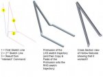
Also, what I did was go back & change my 2nd sketch line (see attached pic) to be mirrored about itself such that when I used the "intersect" command on the 1st & 2nd sketch lines, it created my FINAL sketch line, fully mirrored already!!

Then I used the "Sweep: Protrusion" command & swept a circle along the Left Hand Side final sketched trajectory. Then, using a suggestion from Solidworm, I tried to copy that protrusion & paste it onto the Right Hand Side final sketched trajectory & IT WORKED!!

Then I shelled it & created a cross-section so that folks can see that it came out the way I wanted it!!

Thanks to everyone who assisted in this!!


Joined_Pipes_SOLUTION.jpg
 
Last edited:

Sponsor

Articles From 3DCAD World

Back
Top