Continue to Site

Welcome to MCAD Central

Join our MCAD Central community forums, the largest resource for MCAD (Mechanical Computer-Aided Design) professionals, including files, forums, jobs, articles, calendar, and more.

Can Pro/E do this?

Evan Yares

New member
Pro/E is, in the right hands, incredibly capable -- but how well it can handle really interesting machine design problems?

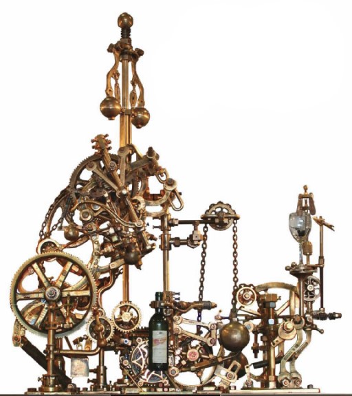
Consider this device:

1in100a.jpg


Here is a video of it.

Believe it or not, it's a corkscrew. A rather Rube Goldbergesque corkscrew, with lots of interesting parts and mechanisms.

If you had to model this machine (with all its kinematics) in Pro/E, how hard would it be?

What parts of it would be challenging?

Where would you need to come up with workarounds?

Where would Pro/E kick-butt compared to other CAD programs?

And how much of the success in doing it would be up to the skill of the user? (That is, would you really need to be a Pro/E wizard to do it right?)
 
I haven't looked at the video, but there's rally nothing
there that seems very difficult. None of the geometry is
very complex. The chains would be challenging, but should
be possible.
 
it's a collection of parts like any other assembly. I'm not saying I could do it since I don't generally do moving stuff and all but if you break down the assembly to the basics, it's parts modeled and assembled together.
 
If all you were doing was reverse engineering the parts,
it'd be pretty easy.

It's the kinematics that are interesting.

First, designing the mechanism so that it would do what
you wanted to do. Second, analyzing the mechanism's
motion, to see that it actually works.

That's the part that I'm really interested in.
 
Evan, what is the underlying question/issue here? Are you trying to compare pro to another cad software? Show us that you did design it, and you are a master?
 
Would that I were a master. I've used dozens of CAD
systems, but I am far from being an expert in any of
them.

Possibly I should introduce myself?

I'm Evan Yares, the new CAD editor for WTWH Media (which
includes MCAD Central, and this forum.)

I have a long background in the CAD industry, starting in
1982. I've done a variety of things in the industry,
including working as a CAD use, a reseller, a consultant,
an analyst (I co-founded Cyon Research and COFES), and a
developer (I was president of the Open Design Alliance,
whose software was once used in Pro/E for AutoCAD
compatibility.)

My perspective on CAD is pretty simple: I think engineers
and designers need tools that help make their jobs
easier. As impressive as todays CAD tools may be, I
think they often miss the mark, when it comes to that
criterion.

The question I asked here, about this strange corkscrew
machine, is a starting point for a series of articles I'm
going to be doing, looking at typical design engineering
problems, and trying to understand the tools, processes,
and resources that are required to tackle them
effectively.

The reasons I chose this example are:

- It's fun and intriguing as an artifact.
- It's geometrically interesting.
- It incorporates multiple mechanism types, including
gears, cams, linkages, and sliders.
- To actually design such a device on a CAD system
(without falling back to seat-of-the-pants guesses),
you'd need to use kinematics, dynamics, and (potentially)
even CFD.

If you're curious, you can watch a 6 minute video, that
shows some of the designers processes in creating this
machine, at
<a href="http://www.bullworks.net/virtual/corkscrew.wmv" target="_blank">this
link.</a>

Now, stepping back to your question: what is the
underlying question/issue here?

I'm just trying to understand how well Pro/E would be
able to handle this type of design/engineering problem.
Not just as an exercise in part modeling, but as a system
-- as a complete product development process.

I'm not looking for a hard and fast answer -- just some
thoughtful input, from people who use Pro/E to make their
living, and who know its strengths and weaknesses far
better than I.

I've asked these same questions, about this machine, in
other forums, where people who are experts in other CAD
systems congregate. I've also asked the major CAD
vendors, including PTC, to get their take on it. (This,
by the way, is not an exercise in bashing CAD vendors.)

Ultimately, I'm going to take the feedback I get here
(and through other sources) and write an article. It will
probably be published in Design World magazine.
 
Evan,<?:namespace prefix = o ns = "urn:schemas-microsoft-com:eek:ffice:eek:ffice" /><O:p></O:p>


As a long user of these tools, I'm confident thatPro/Engineer & Creo can model this mechanism, based on what I can see from the views available with the videos. There would be two "work-arounds" from what I can tell. The first is modeling the chains. Closed-loop chains/belts/cables can be handled, but the open-ended variations of these elementshave not yet been developed in MDX/MDO. Having said this, theoretically it would be possible to model the chains, as they really are, with individual bodies havingproperjoints between them. These chain links would be challenging to model as they come in and out of contact with the pulleys. Even still, there are tools available to model themotion of one object with respect to another to simulate the bodies at the ends of an open-ended chain. The second challenging area is the interaction between the corkscrew and the cork.I can think of a couple different ways I would go about trying to handle this part of the contraption. <O:p></O:p>


Cheers,<O:p></O:p>


Chris
Edited by: Kaz Z06
 
Pro / Creo can handle something like this. ProE's strength is in the
ability to develop with simplified "skeleton" then the rest of the baggage
"other geometry" just goes along for the ride.
 

Sponsor

Articles From 3DCAD World

Back
Top