victor-dot-com
Member
The ID team gives me this vent pattern that I am having a hard time duplicating. A little background first. I get models from ID team, which is created in something other than Creo. I recreate it in Creo, so that engineering can have fully parametric models. With that out of the way, please don't suggest I use the ID model.
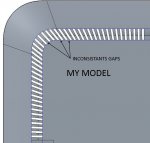
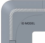
Attached are few images to help explain what I need, and what my problem is. The first image shows the ID model. The ribs are fairly uniform and so are the vent slots. But they are not as perfect as I would like.
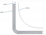
The second image shows how I went about trying to duplicate the pattern. Curve 1, is the curve that controls the angle of the vent, as per ID's instructions. Each slot is made normal to the curve, passing through a point on Curve 2. I first tried putting the points on curve 1, but the results where much worse. The points are created by a fill pattern on the curve.
Image 3 shows the result and the problems, which is non-uniform slots/ribs.
Anyway, I am trying to get uniform slots and ribs. That is the slots all look the same, and the ribs all look the same. Not that ribs look like the slots. One thing you will notice is that the slots on the ID model fan out in width. I have not tried duplicating that yet. I'm trying to get the spacing right first. I'm at a loss as how to accomplish this. Please help.") Thanks.
Thanks.
Victor
Attached are few images to help explain what I need, and what my problem is. The first image shows the ID model. The ribs are fairly uniform and so are the vent slots. But they are not as perfect as I would like.
The second image shows how I went about trying to duplicate the pattern. Curve 1, is the curve that controls the angle of the vent, as per ID's instructions. Each slot is made normal to the curve, passing through a point on Curve 2. I first tried putting the points on curve 1, but the results where much worse. The points are created by a fill pattern on the curve.
Image 3 shows the result and the problems, which is non-uniform slots/ribs.
Anyway, I am trying to get uniform slots and ribs. That is the slots all look the same, and the ribs all look the same. Not that ribs look like the slots. One thing you will notice is that the slots on the ID model fan out in width. I have not tried duplicating that yet. I'm trying to get the spacing right first. I'm at a loss as how to accomplish this. Please help.
Thanks.Victor