Continue to Site

Welcome to MCAD Central

Join our MCAD Central community forums, the largest resource for MCAD (Mechanical Computer-Aided Design) professionals, including files, forums, jobs, articles, calendar, and more.

creating a 2D spiral with pattern and relations.

kfir

New member
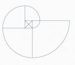
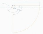
I got an a assignment in which I need to create a 2D spiral in which I can control the number of revolutions, the initial radius and the the increment of radius.
All this only with pattern and relations. this is what I got so far. Capture.jpgCapture1.jpg

I don't know how to make them be in a contentious line. I might be completely wrong here so any help will be much appreciated.
 
You can probably build a Fibonacci spiral using pattern and some clever use of datums, but it might be much easier to build it from equation as already suggested. I'll have a crack at the Fibonacci with patterns
 
Let's say I want to do a Fibonacci spiral like the one in first attachment. I'll start with a sketch that has only the horizontal plane as reference and the datum axis at the intersection between horizontal and vertical plane. You have to dimension the sketch so that it can "freely rotate" without being tied to many references.

You can then pattern the sketch with a 90° increment on the angle offset from the horizontal plane, and a "1" increment for the straight line length. "1" in this case is the size of the center square. The number of patterning entities is the number of arcs you'll end with.

To allow the control you need you'll have to add relations to parameters to control the square size and number of turns.

Hope this helps.
 

Attachments

  • 2016-06-09_104141.jpg
    2016-06-09_104141.jpg
    5.5 KB · Views: 15
  • 2016-06-09_104215.jpg
    2016-06-09_104215.jpg
    8.3 KB · Views: 15
  • 2016-06-09_104234.png
    2016-06-09_104234.png
    8 KB · Views: 12
Dived a bit deeper and here is the result: let's say I want to draw a fibonacci spiral with a defined start radius, radius increment and number of turns.

Define the parameters and add a datum axis at the intersection of top and side plane. Start sketching on the front plane, delete the vertical plane reference and add a reference to the datum axis. Draw a construction circle, size it anyway we'll add relations later. Draw the other part of the sketch, be careful to avoid intent constraint and put dimensions as in the picture. We'll have relations for the circle radius and for the straight line.

Pattern the sketch patterning the 45° dimension with an increment of 90° and the straight line dimension with whatever you want, we'll change it in relations.

Then open the relations dialog and select the features that need relations attached: the sketch and the pattern. The third picture should be helpful in determining what relations drive what, but it's pretty straightforward if you think at how the spiral is built.
 

Attachments

  • a1.jpg
    a1.jpg
    8.6 KB · Views: 9
  • a2.jpg
    a2.jpg
    5.3 KB · Views: 10
  • a3.jpg
    a3.jpg
    15.5 KB · Views: 16
Now, everybody (yes, EVERYBODY) will be wondering: "is it possible to build a fibonacci spiral with equations?" Advantages: you have a single curve and not different arcs, plus with respect to a simple spiral built in equations for each point on a fibonacci spiral the distance between turns is exactly the same.

Of course there are some tricks to use here, but it can be done. First issue is to find a way to "move" the arc origin around the starting square, then the hardest hurdle is to "step" change the radius of curvature. In equations you CANNOT use mod, ceil, floor or trunc statements (actually trunc doesn't exist, I have a complex mix of floor and ceil to substitute that), you can't use booleans. So all is lost? Not at all. Of course I could use some evalgraph magic, but I'd rather build a long, impossible to decipher equation set so that the whole spiral is in asingle datum curve from equation feature.

Here is the equation:

R0=P_R0
RSTEP=P_RSTEP/4
NTURNS=P_NTURNS

narcs=nturns*4
delta=rstep/2

zerox=-sin(t*90*narcs)
zeroy=cos(t*90*narcs)

xstep=if(zerox>0,delta,-delta)
ystep=if(zeroy>0,delta,-delta)

curturndec=t*narcs/40
curturndecn=if(curturndec>1,1,0)+if(curturndec>2,1,0)+if(curturndec>3,1,0)+if(curturndec>4,1,0)+if(curturndec>5,1,0)
curturndecn=curturndecn+if(curturndec>6,1,0)+if(curturndec>7,1,0)+if(curturndec>8,1,0)+if(curturndec>9,1,0)+if(curturndec>10,1,0)

curturn=t*narcs/4-curturndecn*10
curturnn=if(curturn>1,1,0)+if(curturn>2,1,0)+if(curturn>3,1,0)+if(curturn>4,1,0)+if(curturn>5,1,0)
curturnn=curturnn+if(curturn>6,1,0)+if(curturn>7,1,0)+if(curturn>8,1,0)+if(curturn>9,1,0)+if(curturn>10,1,0)

curarc=t*narcs-curturnn*4-curturndecn*4*10
curarcn=if(curarc>1,1,0)+if(curarc>2,1,0)+if(curarc>3,1,0)+if(curarc>4,1,0)

ra=r0+Rstep*curarcn+4*Rstep*curturnn+40*Rstep*curturndecn

ra=if(t==1,ra+Rstep,ra)

x=xstep+ra*cos(t*90*narcs)
y=ystep+ra*sin(t*90*narcs)

Very straightforward :D 
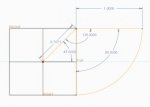
The first part is the trick to "move" the origin, I couldn't use step function so a check on a sinusoidal curve was used. The second part is the toughest: it's used to determine in which "arc" we are to calculate which radius to apply. It does this first determining in which "tens of turns" we are, then in which "turn" and then in which "arc" (a turn is 4 arcs). In this way the curve can have up to 100 turns. Last part is the simple drawing routine. Oh at the beginning global parameters are passed to the local parameters.

Believe it or not, it works!
 

Sponsor

Articles From 3DCAD World

Back
Top