Continue to Site

Welcome to MCAD Central

Join our MCAD Central community forums, the largest resource for MCAD (Mechanical Computer-Aided Design) professionals, including files, forums, jobs, articles, calendar, and more.

Variable pattern in assembly

archibald

New member
Hi,

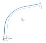
I have to create an assembly (Creo 2.0) for a heat exchanger, which is basically a big, bent pipe (section diameter ~2m) which "coat" itself consists of a great number of small pipes (section diameter ~50mm).

Unbenannt4.jpg

The number of small pipes, their diameter and more are controlled by parameters in the top assembly. Now, in a sub-assembly I'm trying to create said coat of the bigger pipe. My first thought was to create a generic small pipe (as a part), then assemble it and create some sort of pattern that creates all missing pipes following the outer perimeter of the big pipe.

Unfortunately, this would also require that each pattern element automatically changes its dimensions, since a pipe at the upper/outer part of the big pipe would differ from a pipe at the lower/inner part in terms of lenght and diameter.

I've played around a lot, but I can't get it to work properly. I know, for example, that it is possible to control pattern increments via relations, though I've got no idea how this could be useful in my case.

Any help or suggestions for a different approach would be appreciated!
 
Table driven component pattern with family table instances

Here is a suggestion which might help you.

Make a part which is the small pipe and is driven by two curves: the center of the big pipe and the desired diameter of the small pipes. The origin planes of the small pipe model should match with planes in the big pipe. Make the small pipe model so that as you change the dimension which drives the ring location along the curves, the circumference of the small pipe loop changes accordingly. See images below.

Make a family table for the small pipes where the instances are at the desired location along the curves.

Assemble the first instance of the small pipe to the matching planes in the big pipe. Make one of the planes a distance mate with a distance of zero. In order to make the pattern you will need a dimension which is why you need one distance mate. You will not be changing the distance.

Pattern the small pipe using a Table pattern and picking the zero dimension. If you've done things right when you edit the table you will see the name of the instance in the header. Add rows to the table, making all the distances * and using the name of each instance of the small pipe.

Once this is set up you can change the driving curves and regenerate to update all the small pipe parts.
Obviously, other dimensions in the small pipe can continue to be driven by parameters and those parameters can be varied in the small pipe family table.

Tried to upload a zip file containing the Creo files but could not.

Hope this is helpful.
 

Attachments

  • 3-30-2016 16-57-39.jpg
    3-30-2016 16-57-39.jpg
    10.1 KB · Views: 4
  • 3-30-2016 16-57-57.jpg
    3-30-2016 16-57-57.jpg
    7.7 KB · Views: 7
  • 3-30-2016 16-59-34.jpg
    3-30-2016 16-59-34.jpg
    16.6 KB · Views: 8
  • 3-30-2016 17-00-51.jpg
    3-30-2016 17-00-51.jpg
    19.3 KB · Views: 9
  • 3-30-2016 17-02-34.jpg
    3-30-2016 17-02-34.jpg
    17.3 KB · Views: 7
Last edited:
Hi anwyl,

I'm genuinely sorry for not having it made more obvious, but the small pipes which the coat consists of are arranged/aligned in the same direction as the big pipe is. While writing my initial post, I assumed it to apparent because I mentioned it would be for an (exhaust gas) heat exchanger, but that sounds a bit silly now. Sorry!

Here is what it needs to look like:
Unbenannt6.jpg

When creating a single small pipe and making a pattern using an axis it looks like this:
Unbenannt7.jpg

There would be the possibility of creating a skeleton and then creating an individual part for each element of the coat by using copy geometries, but that would be horrible work and wouldn't be flexible at all.

Anyway, thank you very much for your detailed description of using a pattern table, I might be able to exploit this technique in order to solve my problem.

Further help (if you have any ideas) would of course be appreciated!
 
Archibald,

Perhaps the same approach would work with the small tubes as you've shown them: make a single part which, by varying one or two parameters, will have the correct geometry to be any of the small tubes. Then create the family of small tubes and use the pattern table technique to place the instances.

Your initial problem is to find that small tube model. If the big pipe and the small pipes are each planar - each of their individual central curves lies on a plane - then the model should be pretty easy to construct. Attached is an example of such a small tube model. The sweep is in a plane which is parallel to the plane of the big tube. The tube_location csys is offset from the cylindrical csys CS1 and the theta would driven by the family table.
 

Attachments

  • 4-4-2016 12-35-42.jpg
    4-4-2016 12-35-42.jpg
    5.4 KB · Views: 4
  • 4-4-2016 12-37-15.jpg
    4-4-2016 12-37-15.jpg
    9.6 KB · Views: 5

Sponsor

Articles From 3DCAD World

Back
Top