Continue to Site

Welcome to MCAD Central

Join our MCAD Central community forums, the largest resource for MCAD (Mechanical Computer-Aided Design) professionals, including files, forums, jobs, articles, calendar, and more.

3D Revolve?

bsch2734

New member
I was wondering if there is any possible wayin Creo 2 to make a revolve of an object that's already 3D (or something equivalent).
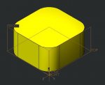
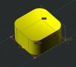
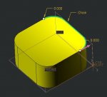
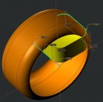
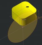
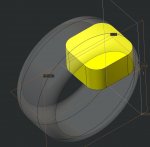
Let's say I have a cube, and I want to revolve the cube around some axis that does not pass through the cube, and then take the solid that could theoretically be created this way and use it. I could probably do the same ting be revolving a few critical cross sections (though I'm not entirely sure about that), but that seems tedious and difficult.
Any suggestions on where to start?
 
you cant use a revolvefeature to revolve a 3d geometry. What you (probably) can do is to make a analysis of the space needed for a 3d part moving (in this case revolve) and then export the result as a step or something, and import it back in to your geometry and solidfy...

//Tobias
 
the same thing goes for when you want to see how much space a front wheel of a car needs when it is making a turn. By doing an analysis of the wheel movement, creo can give you a part of the space needed for the wheel. Cant remember if this option is in the standard pack or if it´s in an extra module....

//Tobias
 
Interesting...
Too bad there's not a more direct way. Definitely a missing feature to me. Can you give me a little more direction on how/ where to get this 3D movement analysis? Maybe direct me to a video or other source with detailed instructions?
Thanks!
 
I can't think of any reason that one would want to do this except to check for clearance. If that is your only purpose, as in the front tire, then a separate assembly with the wheel assembled to one extreme of movement patterned about the axis of rotation will give you what you want. No sense of going through all that is required to get a "smooth" picture when all you want is to know if you have enough room.
 
@moldman - Well , when speaking of the front tyre , the example stated is for clearence check. A patterned wheelmovement around rotating axis wont be enough since the wheel hopefully can move up and down. The thing/option i was talking about (got to look more into it, i just recall from the back of my head that you CAN do this) is that you can state limits for the wheel about rotatingaxis, and also the limits for traveling up and down and so on, and then Creo can give you a part that represents the volume. Offcourse a separate .asm can give you the "result" (most visually imho), but if you want a separate part that is the volume for the complete movement , like when you are modelling the surroundings (fender and so on) then this is probably the way to go. But yes, you can also work with a separate .asm whit a patterned wheel :)

@bsch2734 - If you are trying to make a smooth model, that looks like its a 3d that has been revolved, then you CAN use the same technique. Not saying that you should do it, but you CAN. What you are looking for is a bolean operation in someway, but as you already know, creo cant make it (yet) so you will have to find a workaround.

//Tobias
 
You can do this directly with a VSS.


  • You need a straight line sketch at the axis of revolution as the normal trajectory.
  • Your second trajectory would be the 3D edges that you want to revolve.
  • The sketch of teh VSS would be a single arc or circle with the center at trajectory 1 and the diameter attached to trajectory 2.
 
Hi Doug! would you please upload a simple part showing this?

(or upload some pictures)

//Tobias
 
Last edited:
Sorry for taking so long to respond I've been busy with school.

@moldman- No, I don't just want to check for clearance, and I'm realizing that this application may be a little obscure. I do need a smooth result because the result is going to become a cut into another part, and that other part will ride along the first part like a track.

@tobbo- it seems that, probably due to the limitations of my hardware, a motion envelope isn't going to be smooth like I need it. If I increase the quality level too much, it just never finishes.

@dgs- your idea sounds interesting but when I try to open your file I'm told "This file was created with a commercial version of Creo Parametric and is not compatible with this version" (which is CREO 2.0 student edition). Can you change the file somehow? Or make some explanatory screenshots? Thanks
 
I can't think of any reason that one would want to do this except to check for clearance.
I was looking at a similar feature few years ago when I wanted to model the cut made by a cylindrical tool cutting into material... Basically imagine your tool going straight into the material and then going progressively down in the material...

The solution in my case was to create the curve of the tool trajectory and then repeat my cylinder cut along this curve with a small enough interval to have something almost smooth. It's a bit cheating but gave me quickly the result I needed without using mechanism...
 
Sorry for taking so long to respond I've been busy with school. ...

@dgs- your idea sounds interesting but when I try to open your file I'm told "This file was created with a commercial version of Creo Parametric and is not compatible with this version" (which is CREO 2.0 student edition). Can you change the file somehow? Or make some explanatory screenshots? Thanks

My turn to apologize, work has had me snowed under, no time to model something up.

Let's see if I can explain.

First, you need a solid with some edges that you want to revolve:

attachment.php


Next, sketch a straight line where you want your "axis". You cannot simply use an axis because a VSS requires curves.

attachment.php


Next create a curve by copying the edges that you want to "revolve".

attachment.php


Then create the VSS, which I'll show in the next post since i can't attach more than 4 images.
 

Attachments

  • Capture.JPG
    Capture.JPG
    22.3 KB · Views: 19
  • Capture2.JPG
    Capture2.JPG
    26.2 KB · Views: 18
  • Capture3.JPG
    Capture3.JPG
    25.7 KB · Views: 18
  • Capture4.JPG
    Capture4.JPG
    51.7 KB · Views: 20
  • Capture5.JPG
    Capture5.JPG
    30.8 KB · Views: 18
Funny, it said no more than 4 but it included the 5th anyway. Oh well, here we go.

Time to create the VSS. The "axis" curve is your origin and the normal curve.

attachment.php


In your sketch, the center of your circle should align to the "axis" curve, the diameter should be tied to the other curve.

attachment.php


All done!

attachment.php
 

Attachments

  • Capture6.JPG
    Capture6.JPG
    49.4 KB · Views: 18

Sponsor

Articles From 3DCAD World

Back
Top