I have several parts that I need to model with actual (non-cosmetic) API round thread form tapered thread.
I'm using helical sweep, and the thread profile I'm using is similar to the profile of a tool to cut the threads on a lathe. That is, it incorporates a peak-to-peak profile.
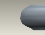
The problem I'm running into is that while the helical sweep works, it leaves a ledge of a bit over a thousandth on the peaks of the threads, as seen here:


I've tried to figure out what I can do to mitigate this by trying out a completely sharp thread, but no dice.
I've tried aligning the thread form to the taper, and also to the axis of the part, but neither one seems to be much different as far as the final thread quality is concerned. I think one or the other of those gave me issues with a failed feature, but I can't remember which one.
I can't attach a file, since the forum limits me to 97.7 KB for a zip file, and the minimal example for this is 278.7 KB, zipped with max compression (it's due to the helical sweep).
I'd be willing to e-mail (or PM, if that's possible) the file to anyone who might be able to shed some light on how to fix this. I've been working on it off and on for a few weeks, and it's getting down to crunch time.
This part is destined, in the long run, for injection molding, but in the near term, it will be a lathe part.
Thanks!
Tracy
I'm using helical sweep, and the thread profile I'm using is similar to the profile of a tool to cut the threads on a lathe. That is, it incorporates a peak-to-peak profile.
The problem I'm running into is that while the helical sweep works, it leaves a ledge of a bit over a thousandth on the peaks of the threads, as seen here:


I've tried to figure out what I can do to mitigate this by trying out a completely sharp thread, but no dice.
I've tried aligning the thread form to the taper, and also to the axis of the part, but neither one seems to be much different as far as the final thread quality is concerned. I think one or the other of those gave me issues with a failed feature, but I can't remember which one.
I can't attach a file, since the forum limits me to 97.7 KB for a zip file, and the minimal example for this is 278.7 KB, zipped with max compression (it's due to the helical sweep).
I'd be willing to e-mail (or PM, if that's possible) the file to anyone who might be able to shed some light on how to fix this. I've been working on it off and on for a few weeks, and it's getting down to crunch time.
This part is destined, in the long run, for injection molding, but in the near term, it will be a lathe part.
Thanks!
Tracy
